MALINYX

Industrial · Hair-styling tool

THERMA

A handheld hair-styling tool whose attachment locks with a three-lug bayonet.

Design study2026Independent project

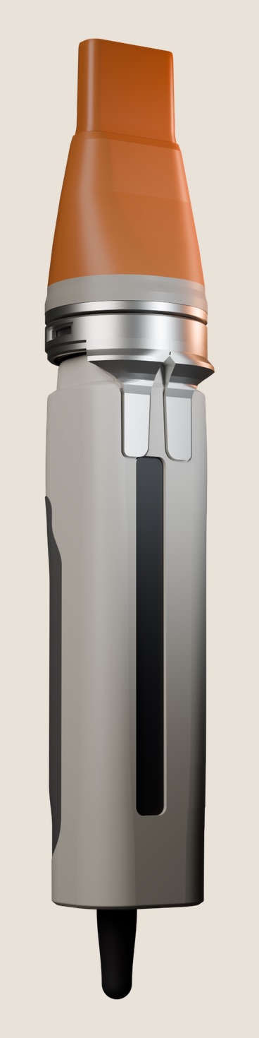
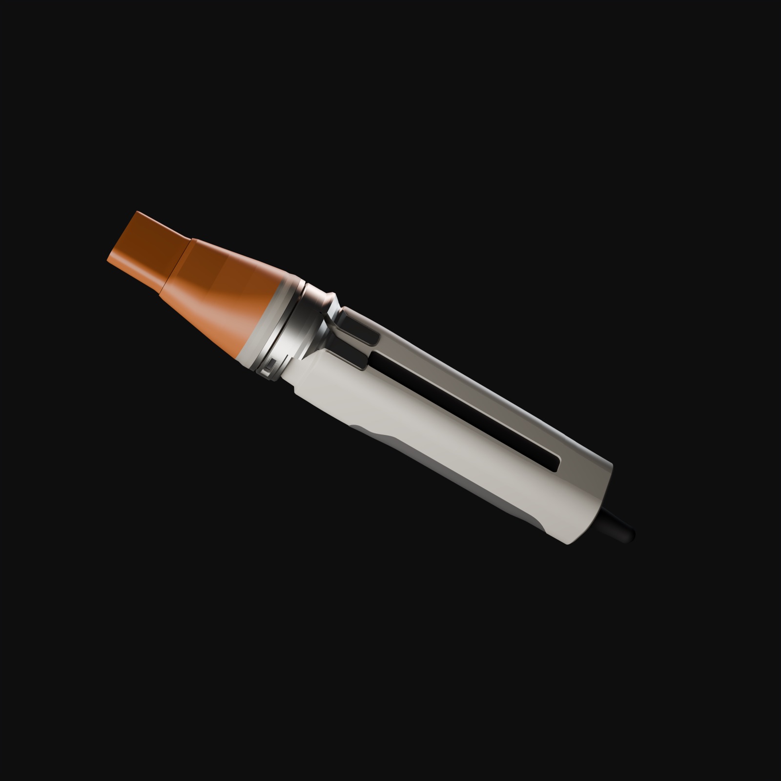
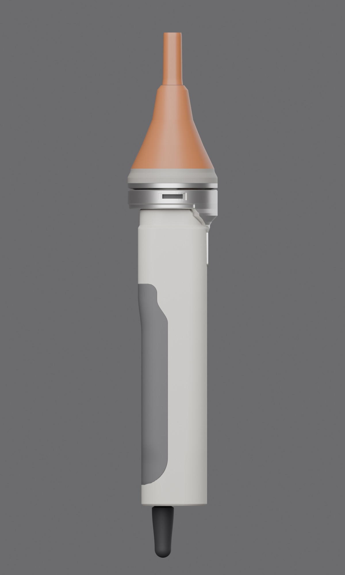
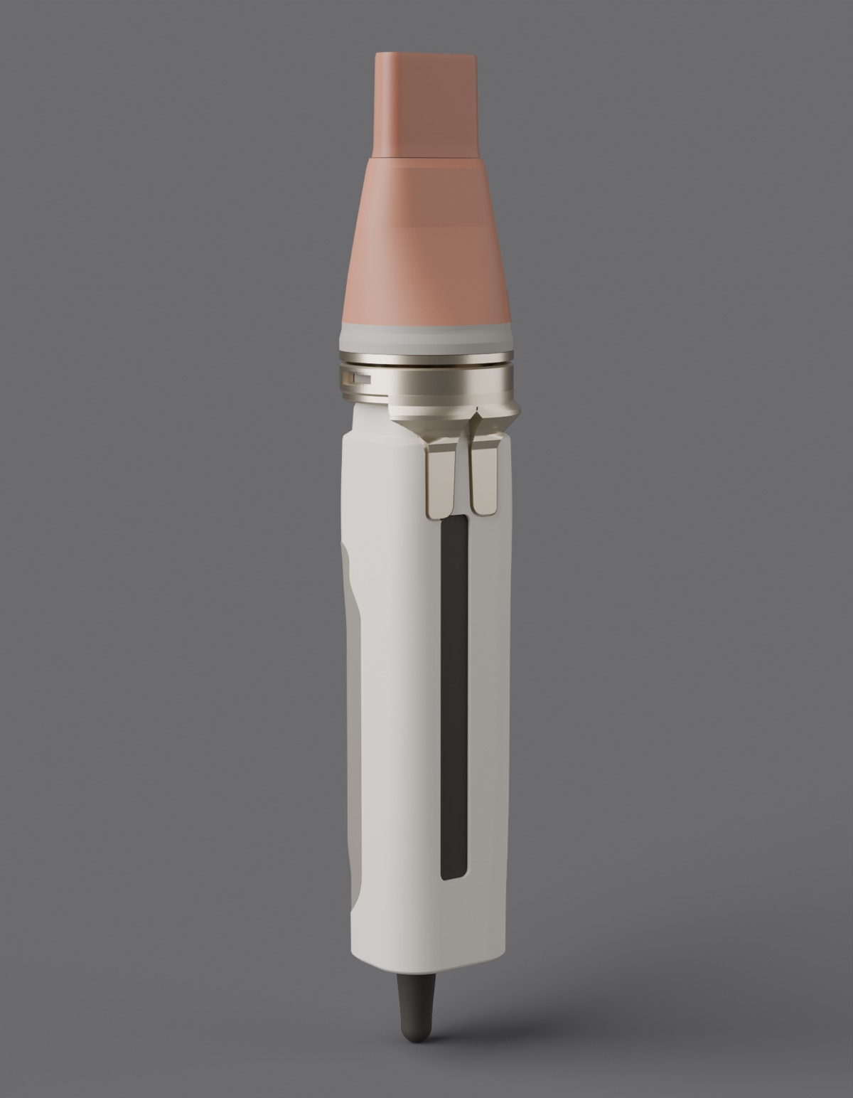
Locked CMF: mineral orange, warm grey, graphite grip, satin aluminium.

01 — The product in 10 secondsTHERMA

Every key dimension a variable. One mineral orange.

What it is
A 40 × 36 × 155 mm handle with a detachable 82 mm airflow concentrator.
Who it is for
People who style their hair at home and need a compact tool with a clear, secure attachment interface.
The problem
An airflow attachment has to lock securely, seal the air path and show at a glance whether it is locked.
What is different
Three lugs, a 30° turn and a 0.40 mm draw-down. A side window shows amber until the attachment is locked.
Lug spacing · three bayonet lugsSpecified intent
120°
Locking rotation · 0.40 mm draw-downModel dimension
30°
Concentrator length, locked after three studiesModel dimension
82 mm
Physical prototypes · performance unsetNot claimed
0
02 — The systemObject → system

How it locks.

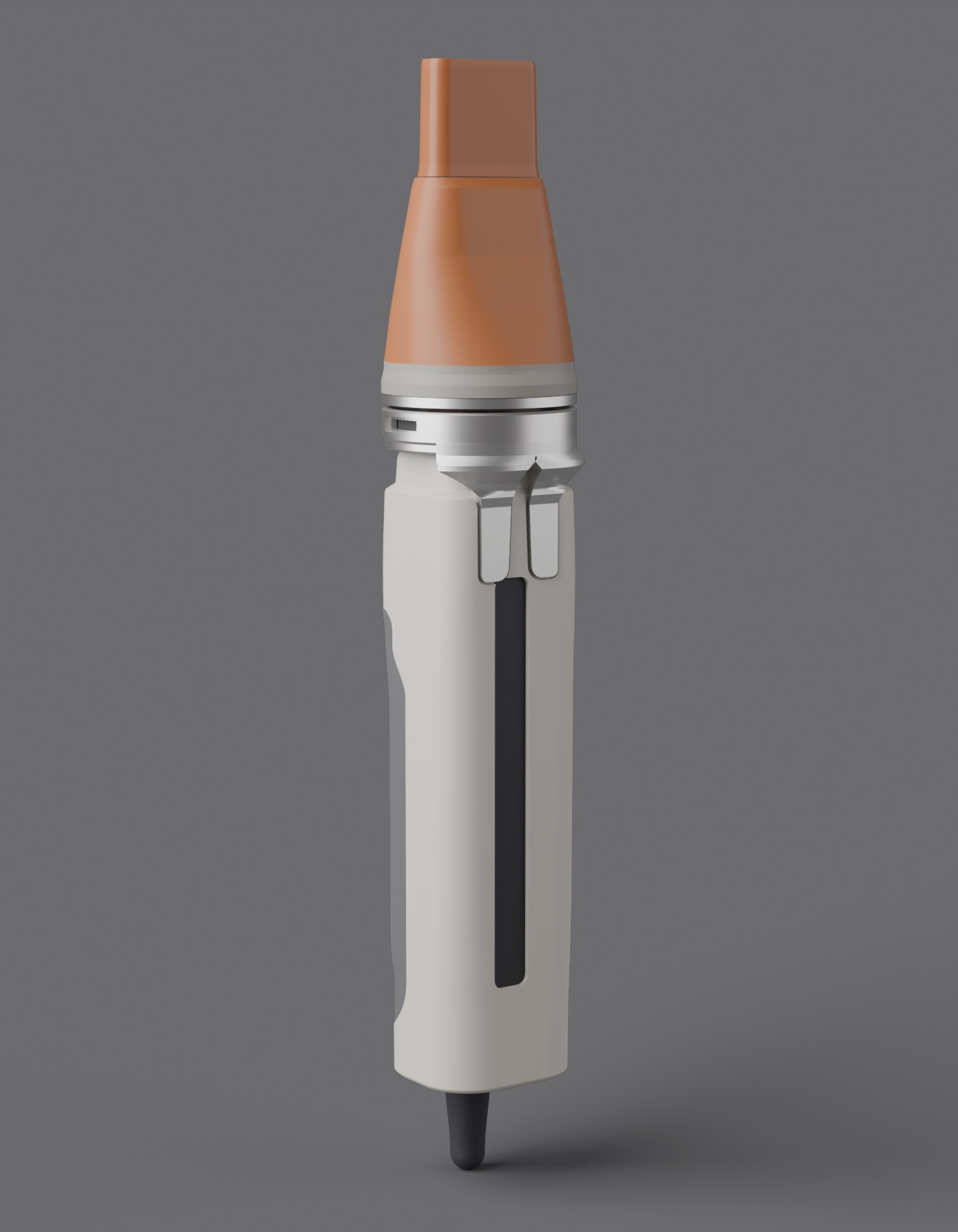
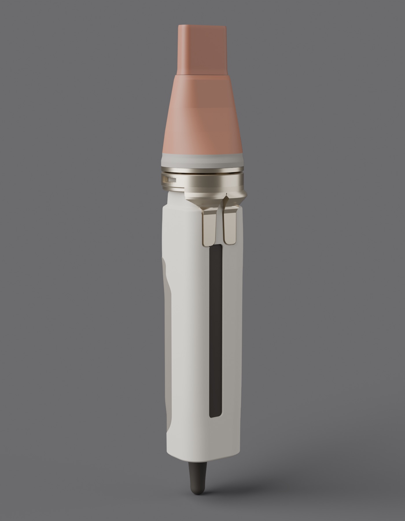
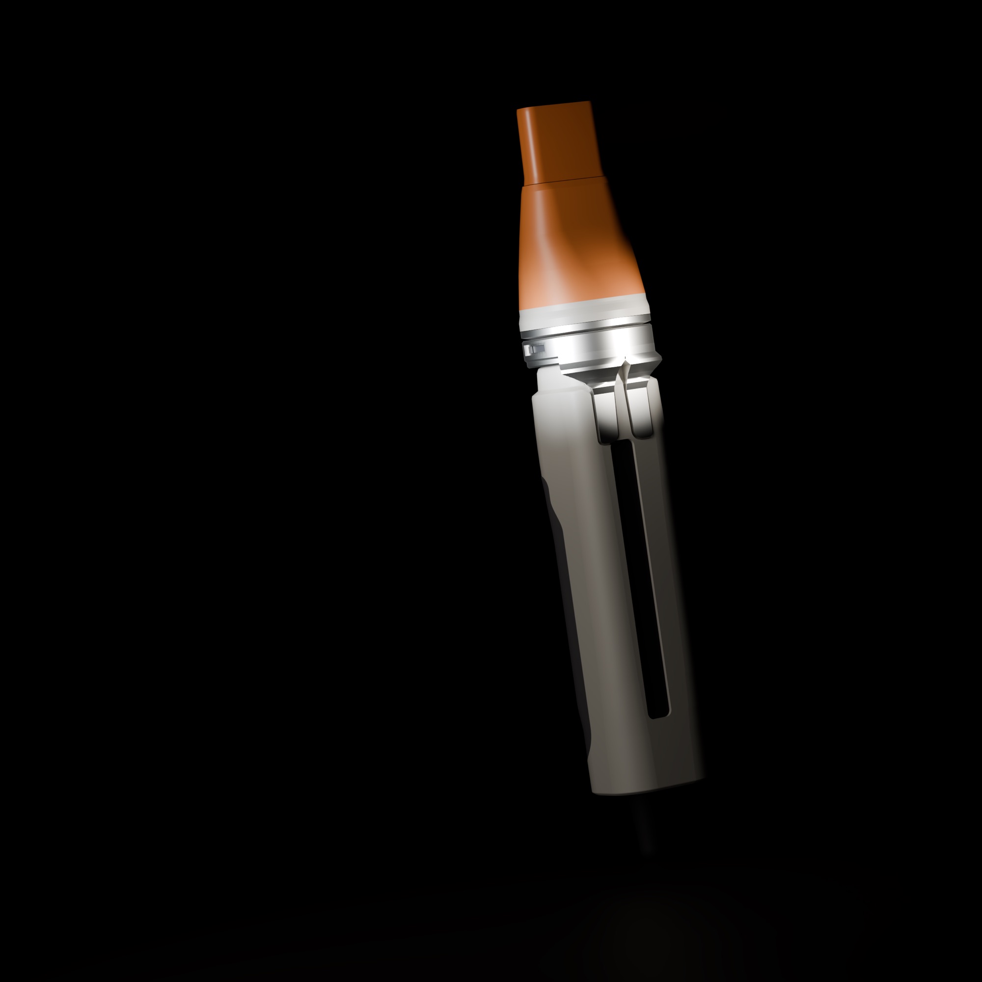
THERMA, three-quarter view: warm-grey handle, mineral-orange concentrator, satin-aluminium collar
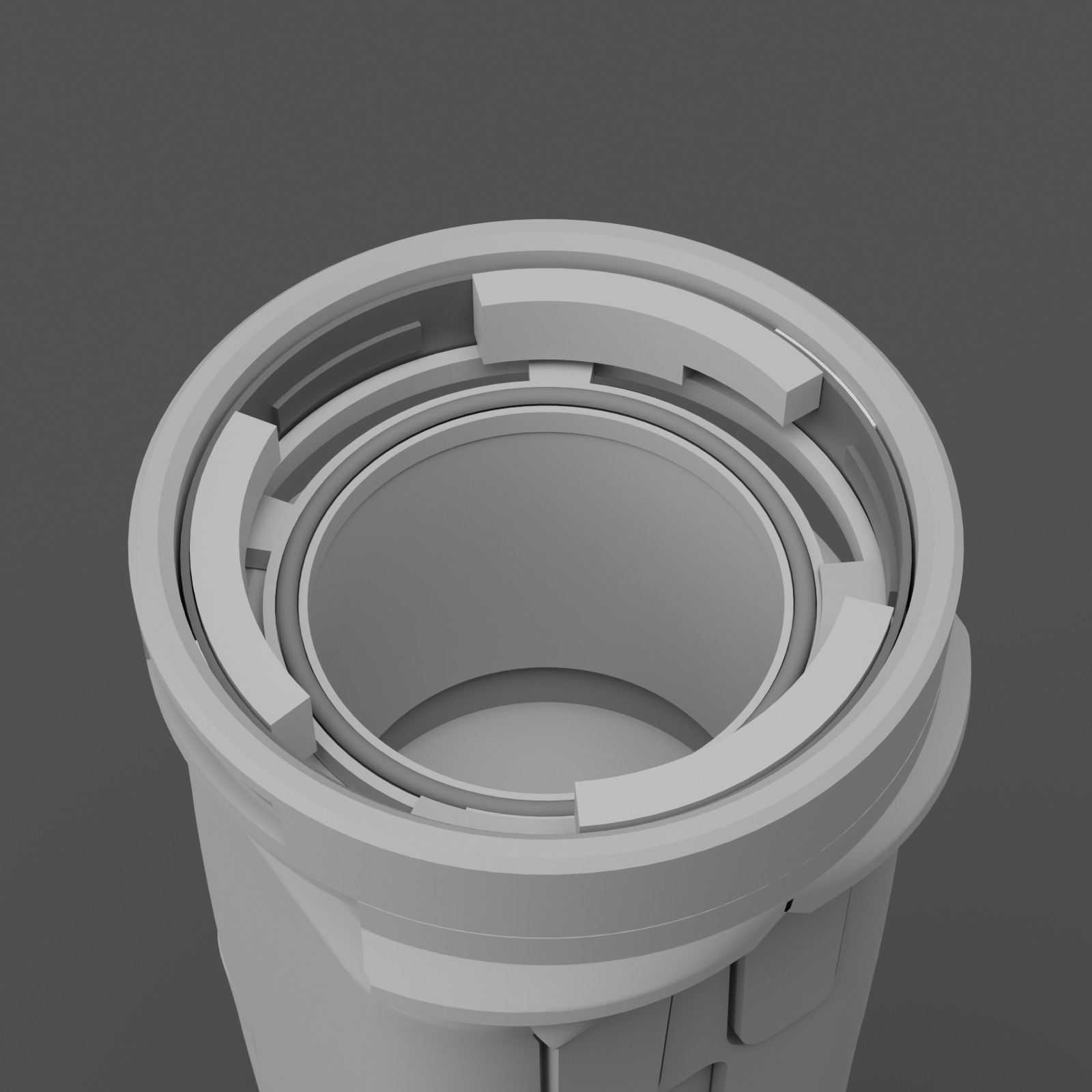
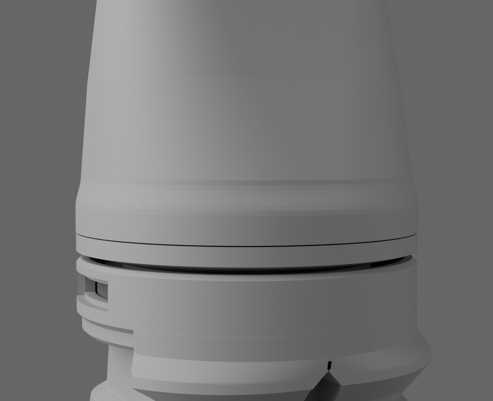
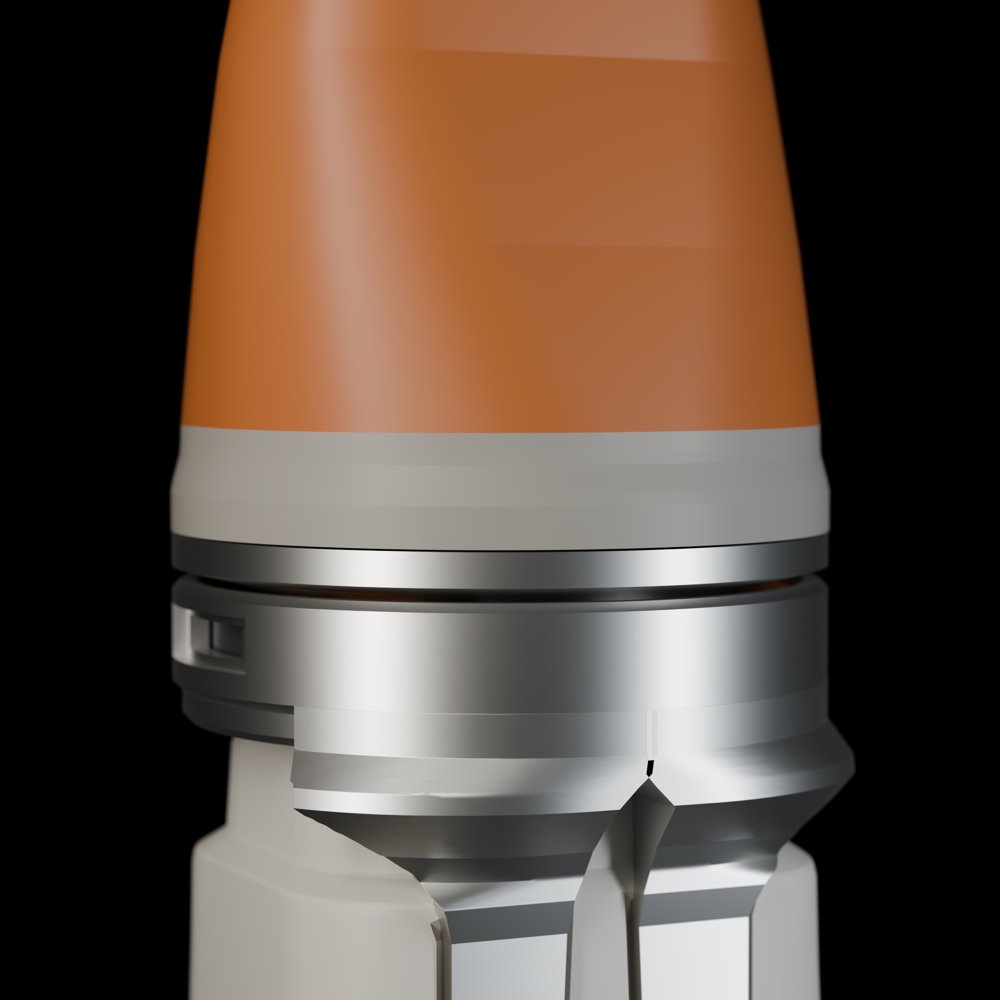
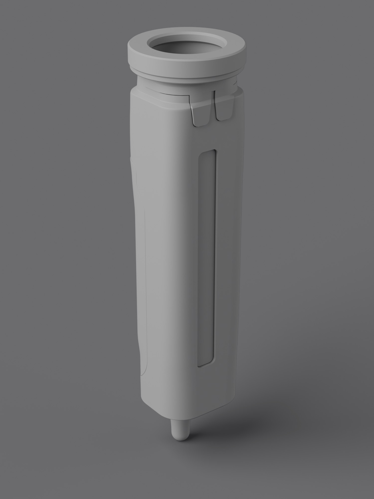
The collar with the attachment removed: three bayonet tracks around the air opening — a clay view of the model
THERMA bayonet, plan from the attachment endLine drawing from the 3D design model. Attachment body, carrier and handle not shown; the attachment is shown by its lugs. Dashed orange: the lugs after the 30° locking turn. Tinted: the track under the flange. Dashed black: hidden edges. Model dimensions in mm, design study, not measured on a part.120°30°Ø2852° ×328°Ø47Ø30.4 MEANVIEW FROM THE ATTACHMENT ENDATTACHMENT BODY NOT SHOWNAir openingLug ×3Lockedposition,dashedBayonetflangeTrack underthe flange,tintedEntry slotSide windowAMBER ARCCollarSealMODEL DIMENSIONS IN MM · DESIGN STUDYNOT MEASURED ON A PART
THERMA bayonet interface, half-section through a lugLine drawing cut from the 3D design model, in the plane 3° short of a lug's stop. Hatched: cut walls; orange: the attachment; dark: the seal; teal: the air path. Detail A, ×4: seal and lug, dashed where the attachment and seal sit before the turn. Model dimensions in mm, design study, not measured on a part.Ø47 COLLARØ28 AIR PATHØ30.4 SEAL, MEAN0.401.521.27DRAW-DOWN 0.40SEAL 1.52 → 1.27SQUEEZE 16 %HALF-SECTION THROUGH A LUG, 3° SHORT OF ITS STOPAAttachmentBayonet flangeCollarLugSignal ringSealCarrierAir ductHandle bodyDetail A, ×4LugShoulderSealDashed: inserted, before the turnMODEL DIMENSIONS IN MM · DESIGN STUDYNOT MEASURED ON A PARTTHERMA bayonet interface, half-section through a lugLine drawing cut from the 3D design model, in the plane 3° short of a lug's stop. Hatched: cut walls; orange: the attachment; dark: the seal; teal: the air path. Detail A, ×4: seal and lug, dashed where the attachment and seal sit before the turn. Model dimensions in mm, design study, not measured on a part.Ø47 COLLARØ28 AIR PATHØ30.4 SEAL, MEAN0.401.521.27DRAW-DOWN 0.40SEAL 1.52 → 1.27 (16 %)HALF-SECTION THROUGH A LUG,3° SHORT OF ITS STOPAAttachmentBayonet flangeCollarLugSignal ringSealCarrierAir ductHandle bodyDetail A, ×4LugShoulderSealDashed: inserted, before the turnMODEL DIMENSIONS IN MM · DESIGN STUDYNOT MEASURED ON A PART
THERMA shell and duct, section on the axisTHERMA concentrator on its bayonet interface, section on the axis plane: an outer shell of 2.6 mm nominal wall and an internal duct of 2.0 mm nominal wall, separated by an empty void; the two come closest, 0.23 mm apart, at the duct's front edge (detail A). The air path runs from a Ø28 mm inlet through the interface to a 26.0 × 6.0 mm outlet slot in a shroud with a 1.55 mm minimum wall; Ø47 mm collar; 82 mm from the collar face to the outlet. Section B–B shows shell, void and duct as concentric rounded rectangles. Model dimensions of a design study, not measured on a part; the void is geometry only and no thermal or airflow performance is claimed.THERMA · CONCENTRATOR ON ITS INTERFACE · SECTION ON THE AXIS PLANE2.62.0Ø28Ø4782ABBOuter shell2.6 nominal wallVoid · thermal breakempty · geometry onlyInternal duct2.0 nominal wallAir pathØ28 → 26.0 × 6.0 slotOutlet shroud1.55 min wallBayonet interfaceØ47 collar · seal · carrierDETAIL A · ×10+0.23min clearanceductshellairvoidSECTION B–BvoidairOUTLET SECTION26.06.0outlet slotcut wallair path, open passage onlyaxisvoid and clearance are geometry only · no thermal or airflow performance claimedmodel dimensions in mm · design study · not measured on a partTHERMA shell and duct, section on the axisTHERMA concentrator on its bayonet interface, section on the axis plane: an outer shell of 2.6 mm nominal wall and an internal duct of 2.0 mm nominal wall, separated by an empty void; the two come closest, 0.23 mm apart, at the duct's front edge (detail A). The air path runs from a Ø28 mm inlet through the interface to a 26.0 × 6.0 mm outlet slot in a shroud with a 1.55 mm minimum wall; Ø47 mm collar; 82 mm from the collar face to the outlet. Section B–B shows shell, void and duct as concentric rounded rectangles. Model dimensions of a design study, not measured on a part; the void is geometry only and no thermal or airflow performance is claimed.THERMA · CONCENTRATORSECTION ON THE AXIS PLANE2.62.0Ø28Ø4782ABB1234561Outer shell2.6 nominal wall2Void · thermal breakempty · geometry only3Internal duct2.0 nominal wall4Outlet shroud1.55 min wall5Air pathØ28 → 26.0 × 6.0 slot6Bayonet interfaceØ47 collar · seal · carrierDETAIL A · ×10+0.23min clearanceductshellairvoidOUTLET SECTION26.06.0outlet slotSECTION B–Bvoidaircut wallair path, open passage onlyaxisvoid and clearance: geometry only,no thermal or airflow performance claimedmodel dimensions in mm · design studynot measured on a part
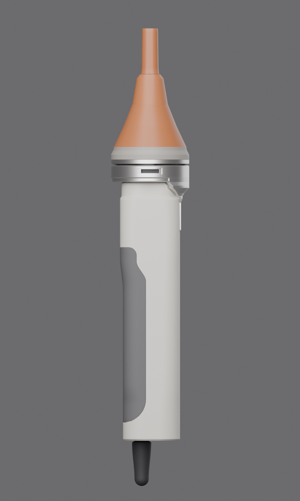
THERMA in its locked CMF
  1. 01 / 07

    The object

    A 40 × 36 × 155 mm handle and one detachable airflow attachment — the only coloured part.

  2. 02 / 07

    The attachment comes off

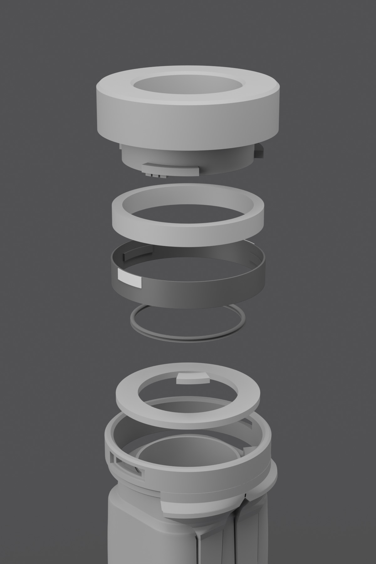
    Without it, the collar shows the interface: the Ø28 mm air opening, the seal and three bayonet tracks.

  3. 03 / 07

    Three lugs, 120° apart

    The attachment enters on three lugs spaced 120° apart, so it seats in any of three positions.

  4. 04 / 07

    A 30° turn locks it

    Turn it 30°: each lug runs along its track to the locked position, and the amber signal arcs swing clear of the side windows.

  5. 05 / 07

    Drawn down onto the seal

    The same turn draws the attachment 0.40 mm down: its shoulder meets the Ø30.4 seal, and the helical track squeezes it from 1.52 to 1.27 mm.

  6. 06 / 07

    Air straight through

    The air path runs Ø28 mm through the collar to a 26 × 6 mm outlet slot. A void runs between the shell and the duct wall (2.6 and 2.0 mm nominal); they come no closer than +0.23 mm — geometry only.

  7. 07 / 07

    The finished object

    Every value here is a model dimension or a specified intent. Nothing has been built or tested.

The drawings are traced from the 3D model’s own geometry: model dimensions, not measurements. Switch to Evidence to see their dimensions.

03 — The design challenge

A head that locks, seals and shows it.

The concentrator carries the airflow, so the interface must hold it, seal the Ø28 mm air path and make its lock state readable. The handle was developed in controlled 3D geometry iterations — proportion, bridge, interface, concentrator, CMF — each frozen after a side-by-side comparison, so later decisions never reopened earlier ones.

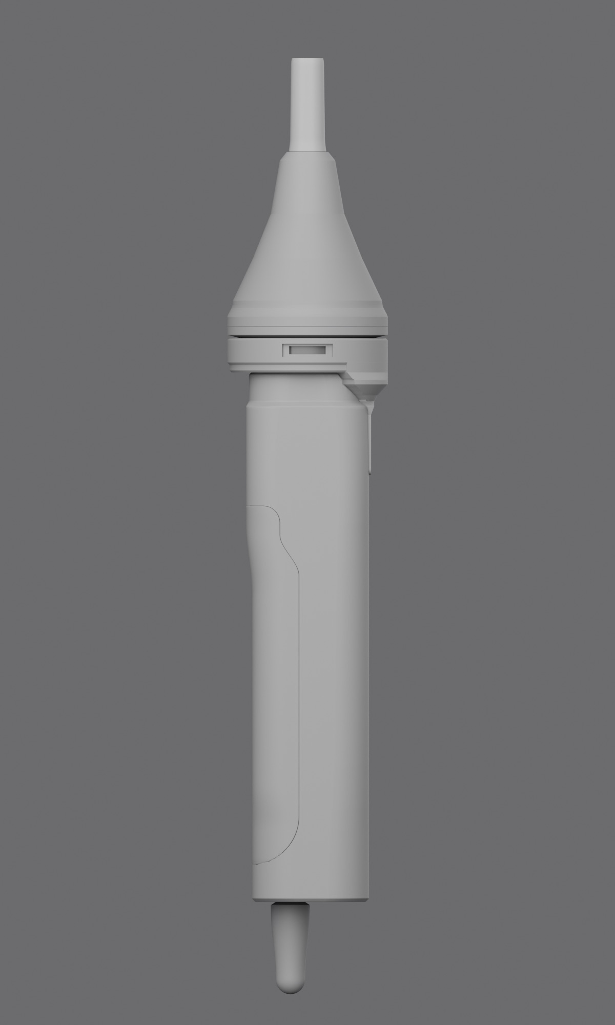
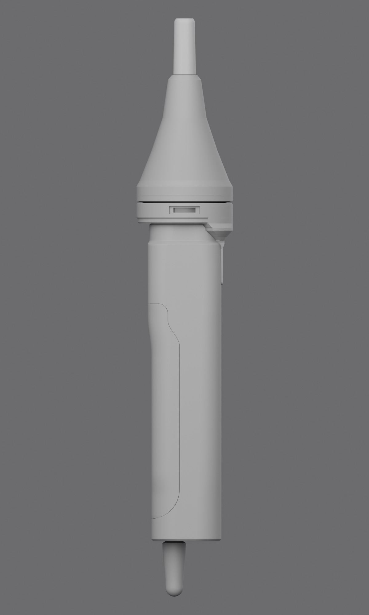
The frozen body, orthographic side: 155 mm handle, Ø47 collar, 82 mm concentrator
04 — My contributionIndependent project

What I did.

Self-initiated · no client

  • Industrial design and form language
  • Bayonet interface architecture
  • 3D development · key dimensions as variables
  • CMF study and locked direction
  • Geometry study of the frozen shell
  • Visualisation
05 — Design response5 decisions · reason · evidence

The decisions that shaped it.

Decision 01

Three-lug bayonet

Three lugs at 120° spacing give the interface rotational symmetry. A separate 30° turn locks the attachment and draws it 0.40 mm down onto the seal.

Specified intent · modelled, never built
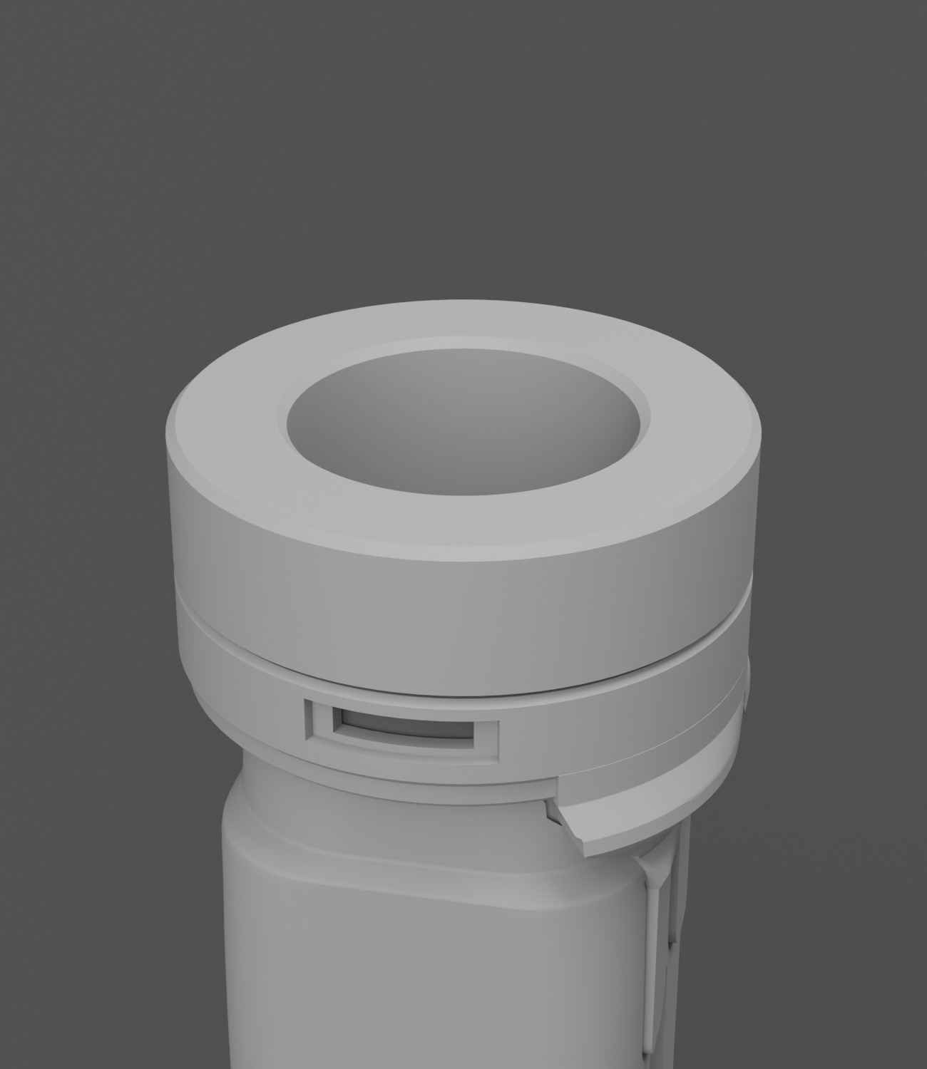
Interface, locked: the attachment turned 30° and drawn down

Decision 02

A lock you can read

Amber arcs sit behind two 28° side windows while the attachment is unlocked and swing clear when it locks, so the lock state reads at a glance.

Specified intent
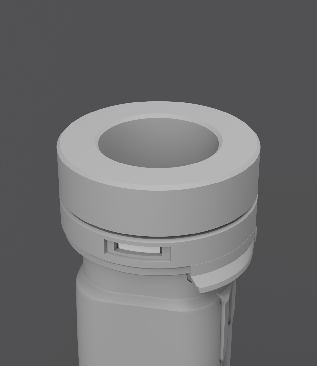
Interface, unlocked (clay): the signal arc sits in the side window — its amber is specified, not rendered here

Decision 03

Air through the interface

A Ø28 mm air path runs clear through the collar; contact pins (Ø1.5) sit in pockets, their faces 0.95 mm below the top of a 0.5 mm wall.

Specified intent
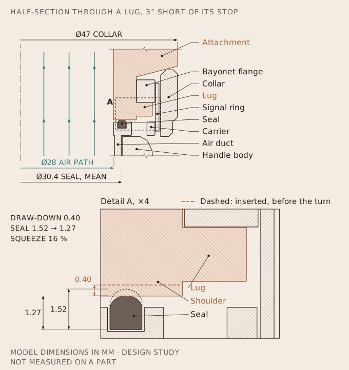
Half-section through a lug, locked: the air path through the collar, the seal and the lug in its track — a line drawing traced from the model

Decision 04

A fork, not a bolt-on

The bridge emerges from under the collar and joins into one root — a Y-crotch — that never exceeds the collar’s Ø47.

Designed
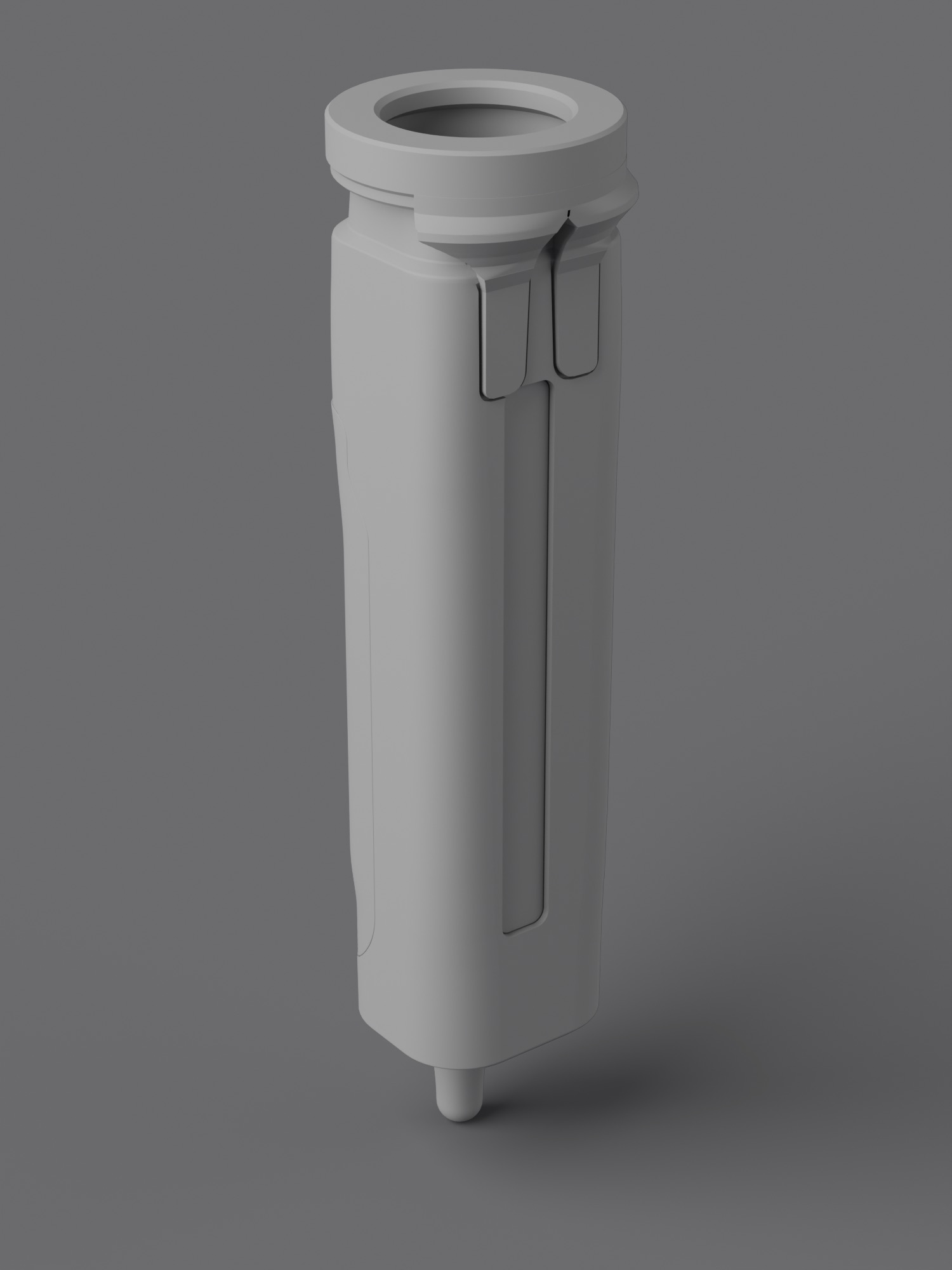
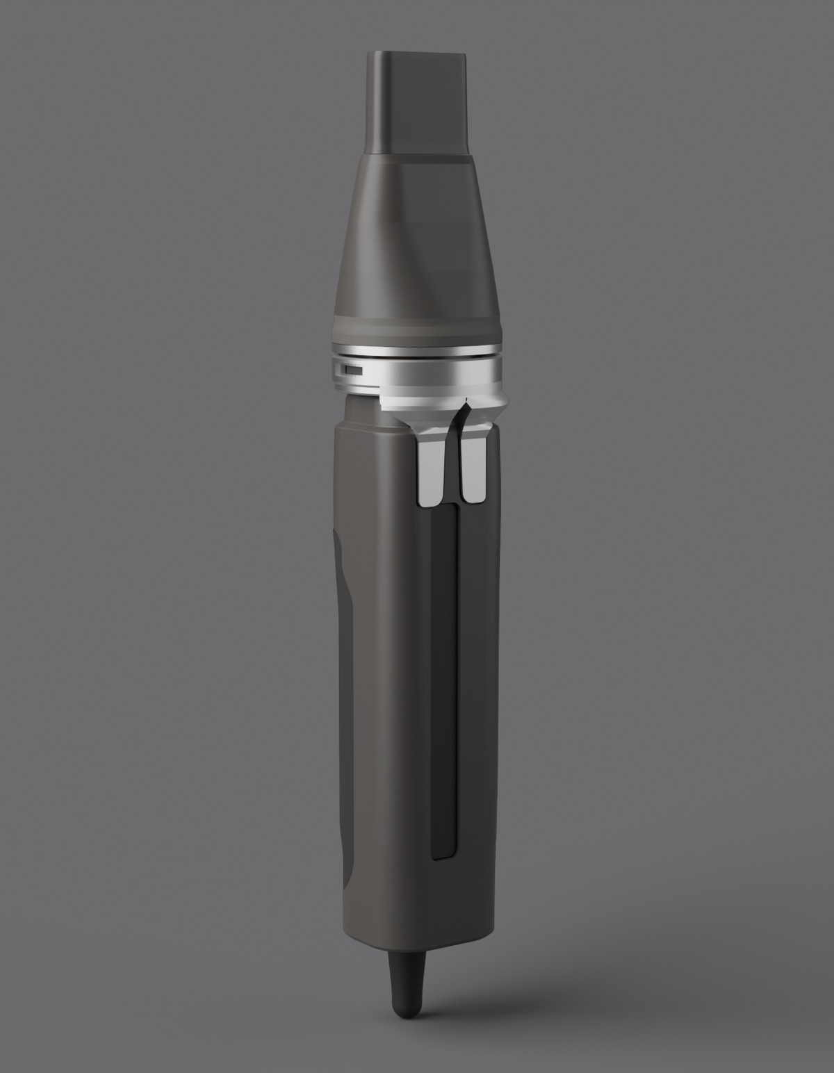
The selected fork bridge, grey clay

Decision 05

A geometric thermal break

A void runs between the shell and the duct wall (2.6 and 2.0 mm nominal). At their closest, measured normal to the surfaces, they are +0.23 mm apart. It is geometry only: no thermal performance is claimed.

Designed · geometric only
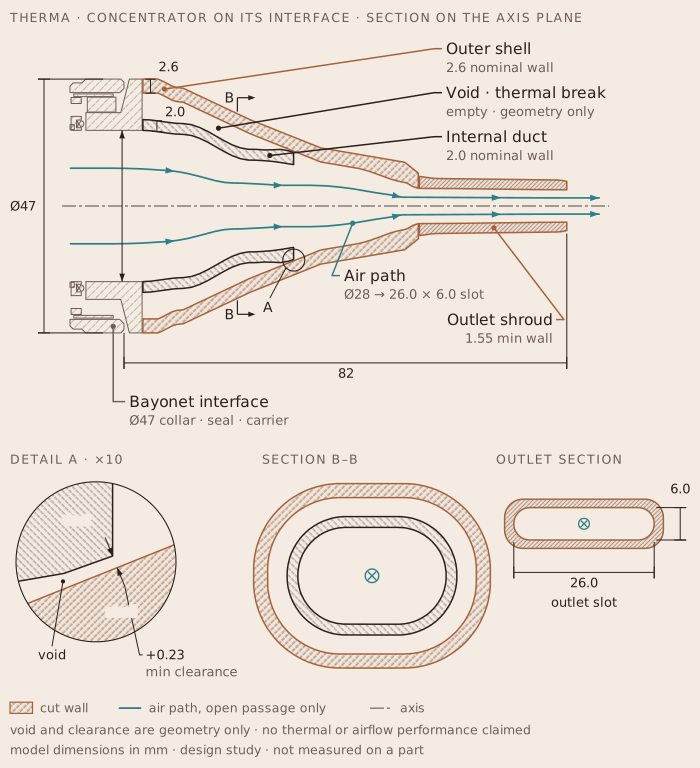
Shell, void and duct on the axis plane, with the air path to the outlet slot — a line drawing traced from the model
06 — Form developmentWhat changed, and why

Iterations that explain the final geometry.

Proportion

Before any detail, the first base was re-proportioned: collar depth 15 → 10 mm, front transition 13.5 → 10 mm, control spine 114.5 → 100 mm.
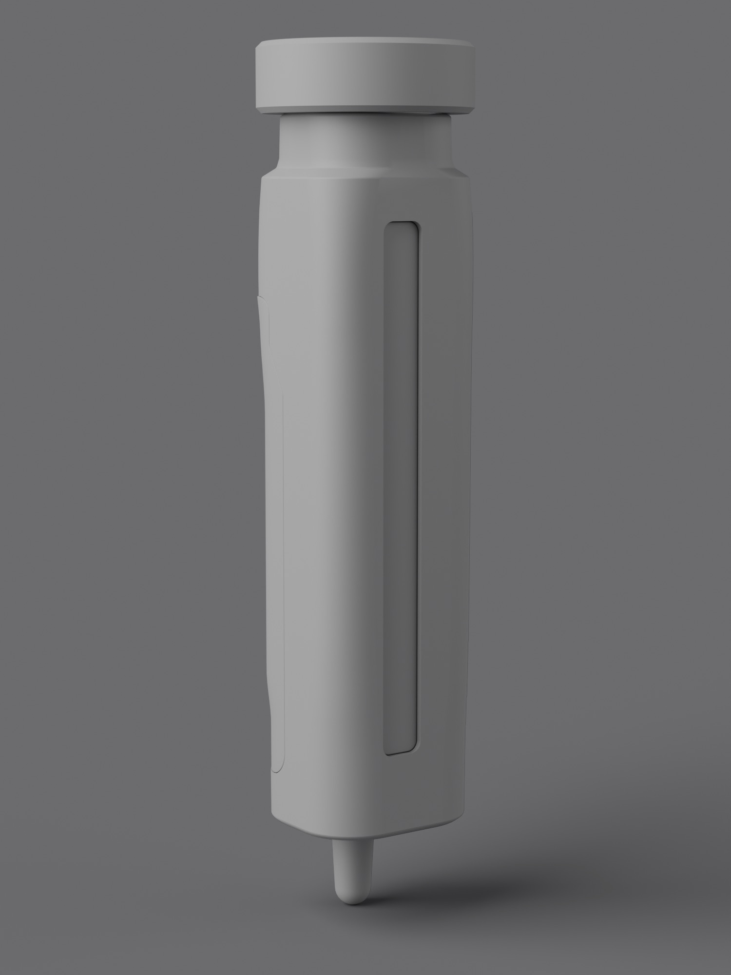
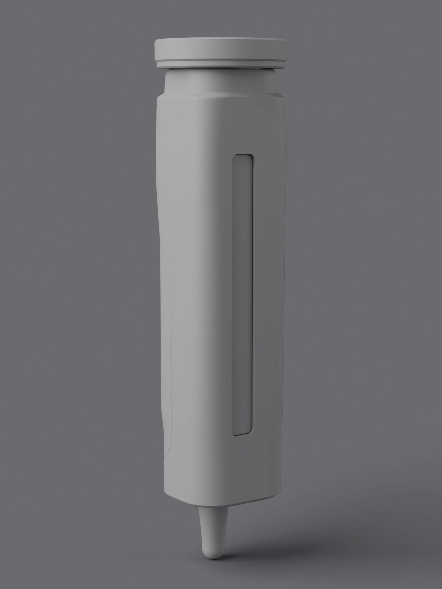
Proportion · first base
Proportion · re-proportioned

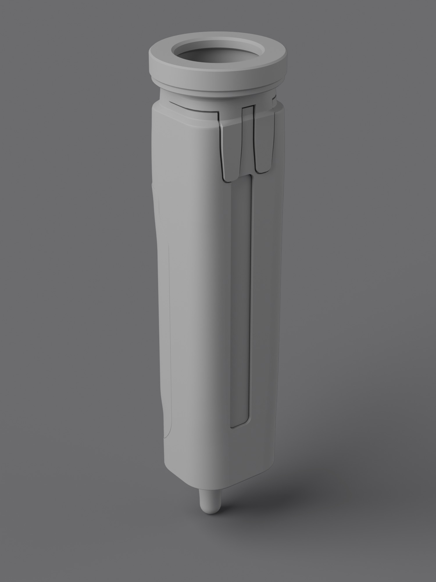
Bridge

Five bridge variants were compared under identical cameras. B1 was short (18 mm penetration, 2 × 9.5 mm legs); B2 long (30 mm), with a central field. The selected B2.2 fork joins its legs into one root under the collar, with a 0.70 mm shadow gap.
Bridge · B1 short
Bridge · B1 short
Bridge · B2 long
Bridge · B2 long
Bridge · B2.2 fork, selected

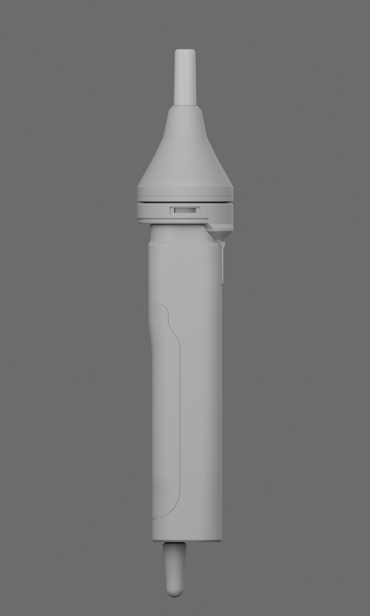
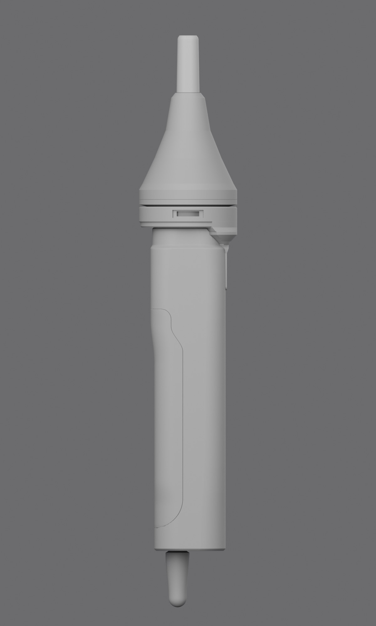
Concentrator length

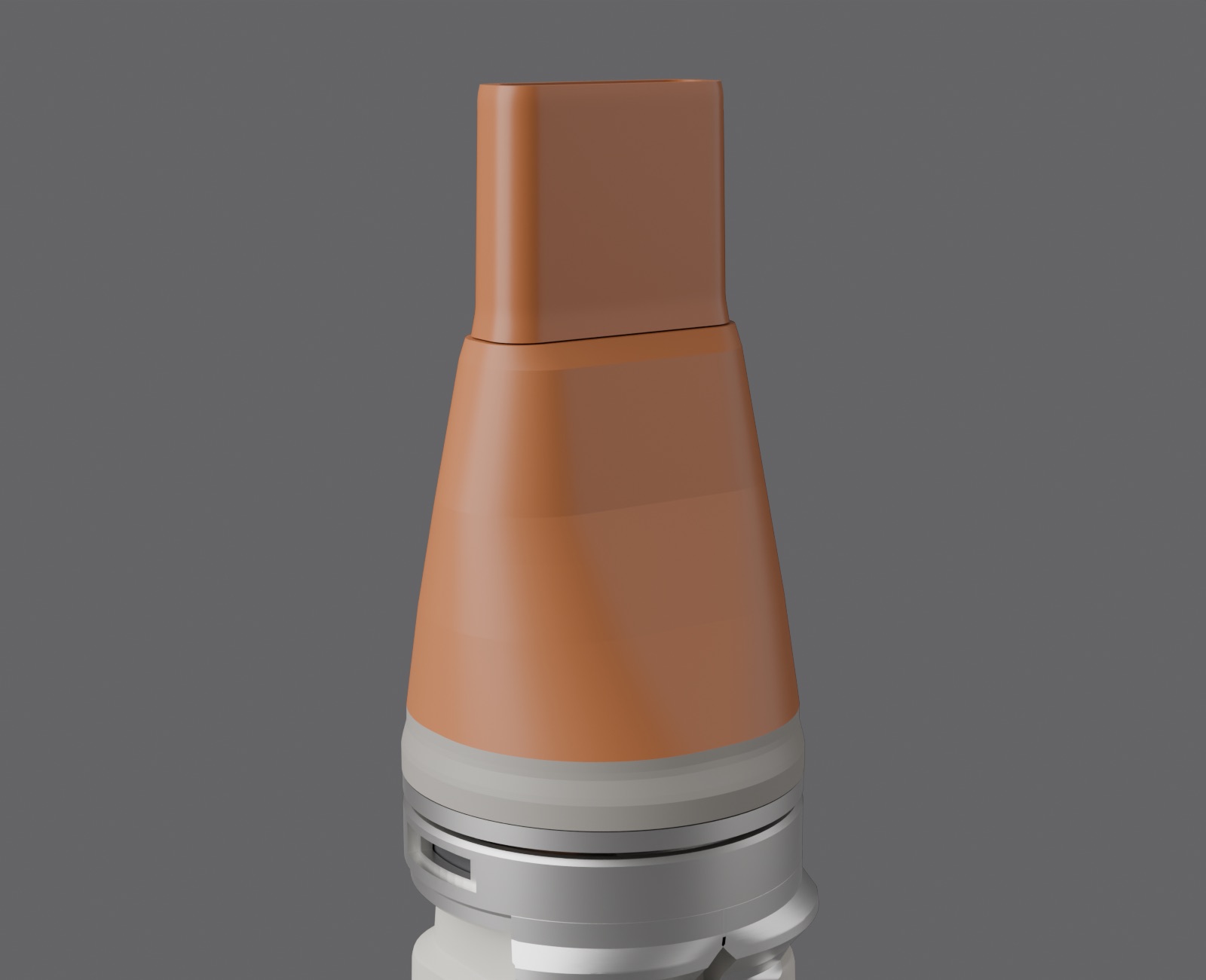
Only the transition length varied. 75 mm compresses the three cones into one dome; 90 mm drifts toward a bottle silhouette; 82 mm keeps the rate changes legible — locked.
Concentrator length · 75 mm
Concentrator length · 82 mm, locked
Concentrator length · 90 mm

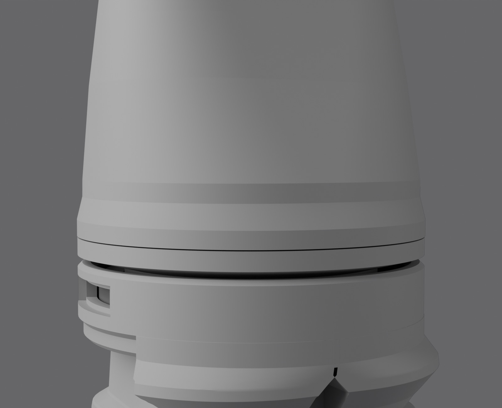
Shoulder

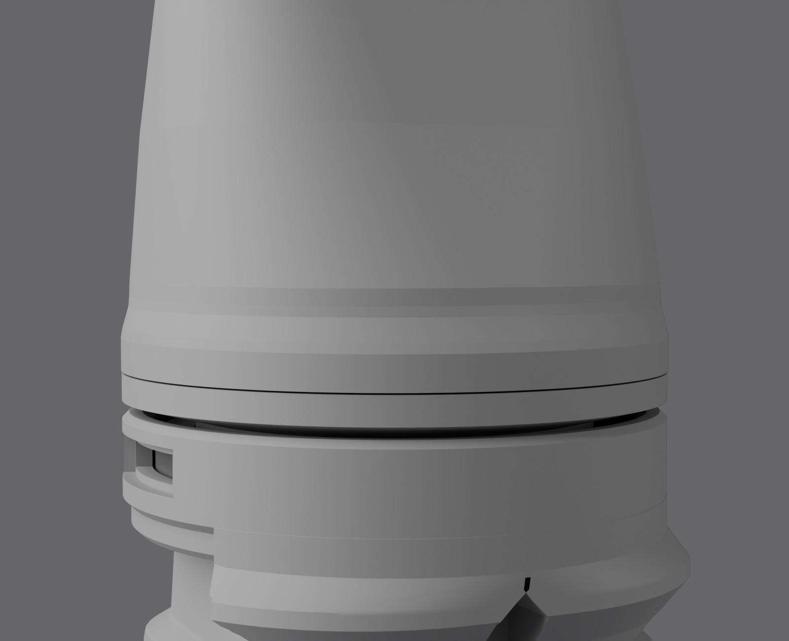
Three shoulders on the same 7.5 mm zone — crisp, balanced and soft. The balanced one, a 2.8 mm land and a 3.4 mm eased facet, was selected.
Shoulder · crisp
Shoulder · crisp
Shoulder · balanced, selected
Shoulder · soft
Shoulder · soft
07 — Product architecture & engineeringDesign study

How it is built.

THERMA, side view in the locked CMF
THERMA side view, section layerTHERMA side view, technical layer: the section on the attachment axis traced from the model through the render's own camera. Outer shell (2.6 mm nominal wall), internal duct (2.0 mm nominal wall) and the empty void between them; the interface stack (collar, seal, carrier, signal ring, mating boss; lugs dashed, off the cut); the air path from the bore in the handle through the Ø28 mm collar opening to the 26.0 × 6.0 mm outlet slot; 82 mm concentrator, 155 mm handle, Ø47 mm collar. Model dimensions of a design study, not measured on a part.82155Ø47Ø28model dimensions in mm · design study · not measured on a partOutlet slot26.0 × 6.0Outlet shroud1.55 min wallOuter shell2.6 nominal wallCollarInternal duct2.0 nominal wallVoidempty · geometry onlySealCarrierAir pathØ28 → 26.0 × 6.0 slotHandlesolid below the boreLugsdashed · off the cutSECTION ON THE AXIS PLANE
Drag across the side view. Underneath is the section through the attachment axis — shell, duct, air path and interface — traced from the same model, through the same camera.

A 3D-developed design study. The interface was frozen after three iterations and checked on the model. Nothing has been built or tested: every value below is a model dimension or a specified intent, never a measurement of a part.

Key dimensions and their claim level
ItemValueLevel
Handle envelope40 × 36 × 155 mmModel dimension
CollarØ47 mmModel dimension
Lug spacing120° · three lugsSpecified intent
Locking rotation30° · 0.40 mm draw-downModel dimension
SealØ30.4 · 1.52 → 1.27 mm (16 % squeeze)Specified intent
Air pathØ28 → 26.0 × 6.0 mm outlet slotModel dimension
Shell-to-duct clearance+0.23 mm, normal to the surfaces · geometric onlyMeasured on model · minimum
Shroud wall1.55 mm minimumModel dimension
Interface stack, micro-exploded: shoulder, bayonet flange, track, seal, signal ring, carrier
Engineering notes the longer story

THERMA is a 40 × 36 × 155 mm handle with a detachable airflow attachment. Every key dimension is a variable, and every stage was frozen only after a side-by-side comparison: five bridge variants led to one fork, three interface iterations to a three-lug bayonet, three concentrator lengths to 82 mm.

Behind the exterior sits a geometry study, revised through several review rounds, of whether the frozen shell can hold a real product: a lateral clamshell split, a lofted cavity and a register of conflicts. Flow, heat, power, noise and safety are not established.

08 — CMFColour · material · finish

Material with a job.

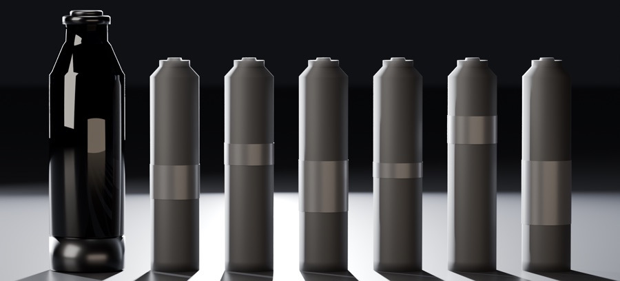
Three CMF directions were compared under one camera and one lighting set, then refined in a micro-study. No pure black, no pure white; the rejected directions are shown below.

  • Mineral orange#A6633B

    Attachment shell · Roughness 0.42

    A mineral orange rather than a safety orange: the attachment is the one coloured part.

  • Warm grey#C7C2BA

    Handle body

  • Graphite#575659

    Grip

  • Signal amber#E6852E

    Lock-signal arcs · Seen only through the side windows

    Colour as state: it shows only while the attachment is unlocked.

  • Satin aluminium#D1D0CE

    Fork and collar · Satin anodised — a finish direction, not a compliance claim

    Moved from polished to satin in the refinement study.
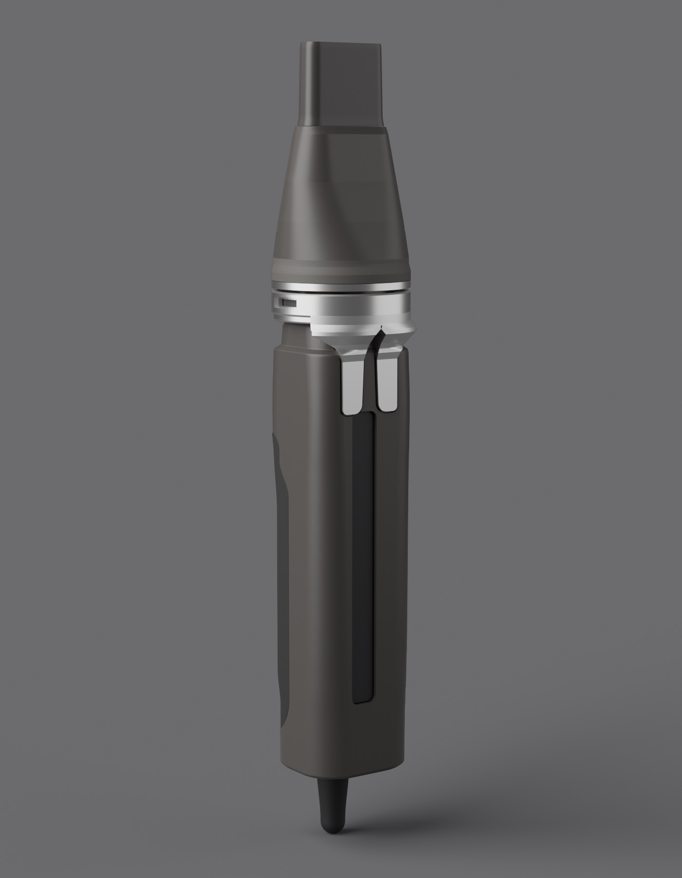
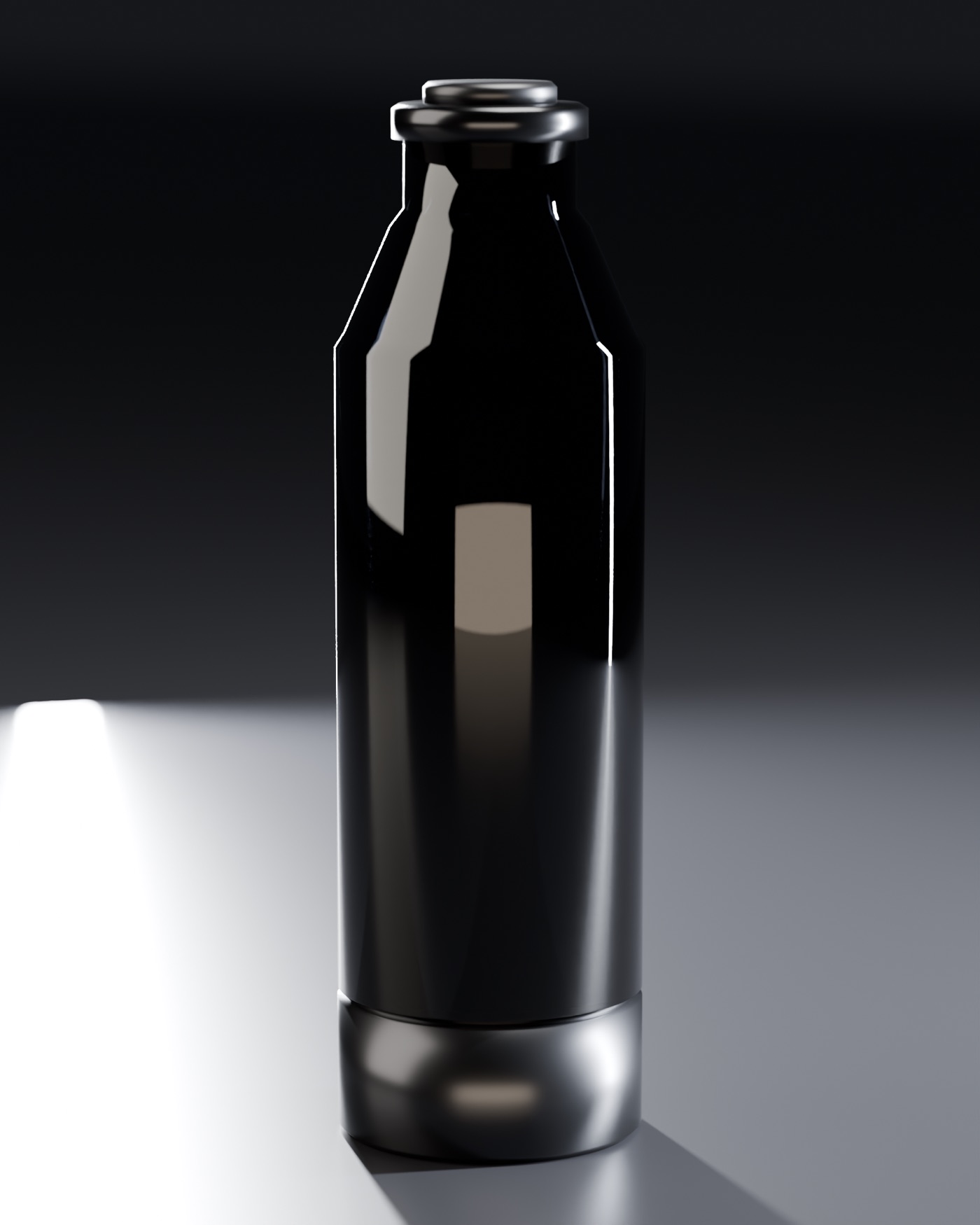
Direction B · rejected: all-dark body
Direction C · rejected: bone and rose clay
Locked CMF
Locked CMF

10 — Project status

Design study
Stage
Design studyOne question taken deep — a mechanism, an interface, a form or a colour system — in CAD or drawings. Not a complete product.
Role
Industrial design, 3D model (Rhino), CMF, geometry study
Project type
Independent project
Year
2026
Tools
Rhino (3D model)
What exists
A 3D model, available in Rhino, with a frozen interface, a locked CMF and a geometry study of the frozen shell.
Physical evidence
None — no physical prototype.
Not claimed
  • Airflow, heating or temperature rise
  • Power, noise, mass or duty cycle
  • Safety or compliance
  • Manufacture
Still open
  • Attachment 02 not started.
  • Performance requirements — flow, temperature rise, power, noise, mass — are unset.
  • A 0.35 mm detent is specified but not yet in the model: the entry slot cuts it away.
  • Prototype validation required: lug engagement, seal squeeze and the feel of the lock.
Images
Renders of the THERMA 3D model, available as a Rhino model (design study); the technical diagrams are drawn from the same model geometry. The six-image art set was rendered from the locked CMF model in a separate, AI-assisted workspace: these are renders of the model, not AI-generated images.