MALINYX

Product · Desk lamp

AXON

One ring sets height, tilt and direction.

CAD-developed concept2017 conceptIndependent project

Designed and analysed — prototype in progress

AXON at TASK: render from CAD, clay toned by function
Render from CAD

TASK · ring at 170°

Turn the ring: drag round the dial, or ← → · Page Up / Down: the next pose

The sweep: STOWED → TASK → AMBIENT and back, one frame per degree of ring angle. Render from CAD, clay toned by function.
01 — The product in 10 secondsAXON

One ring. Three poses.

What
A desk lamp driven by one ring round its base.
How
The ring is a cam drum: its grooves move the sleeves, the pan and, through a rack, the head's tilt.
Holds
By geometry: no brake, no balance spring. The locking flanks are cut under the friction angle.
Status
Designed and analysed. Nothing is measured yet; the prototype is next.
One ring, three outputs: height, tilt and directionDesigned · kinematic model
1 → 3
Ring travel between its end stopsDesigned · kinematic model
270°
Poses held by geometry: no brake, no balance springSpecified intent · provisional friction
3
Head rise from STOWED to TASKSpecified intent · kinematic model
180 mm

02 — Origin

2017 → 2026

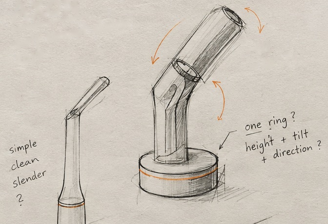
AXON is a name I've carried for more than fifteen years, first as a business idea. The lamp came in 2017: one ring that sets height, tilt and direction. I began engineering it in late 2025; in 2026 it became a frozen, checked CAD.

In the designer's words
The idea as first imagined — redrawn in 2026 (AI-assisted).
The idea as first imagined — redrawn in 2026 (AI-assisted).AI-assisted visual

03 — The thesis

One input, three outputs

Turn the ring. Height, tilt and direction follow.

From STOWED to TASK the head rises 180 mm and tilts 30° while the pan holds at 0° (θ 0–172°). Then the pan turns 180° by θ 268°, as the head rises 60 mm more.

Height, tilt and direction against the ring angle Three panels over the ring angle θ from 0 to 270°. h rises from 160 mm at STOWED to 340 at TASK and 400 at AMBIENT; the tilt φ goes from -90° to -60° and +30°; the direction β holds at 0° up to θ 172° and turns to 180° by θ 268°. 160 340 400 hh (mm) -90 -60 30 φφ (°, + up) 0 180 ββ (°) STOWED 0° TASK 170° AMBIENT 270° the pan holds at 0° ring angle θ, 0–270°, one sample per degree Height, tilt and direction against the ring angle Three panels over the ring angle θ from 0 to 270°. h rises from 160 mm at STOWED to 340 at TASK and 400 at AMBIENT; the tilt φ goes from -90° to -60° and +30°; the direction β holds at 0° up to θ 172° and turns to 180° by θ 268°. 160 340 400 hh (mm) -90 -60 30 φφ (°, + up) 0 180 ββ (°) STOWED 0° TASK 170° AMBIENT 270° the pan holds at 0° ring angle θ, 0–270°, one sample per degree
h, φ and β against the ring angle θ, one sample per degree, the three detents marked. Chart from the kinematic model's results Specified intent · kinematic model
The three poses ring angle, height, tilt, direction
The three poses
Poseθhφβ
STOWED0°160 mm-90°0°
TASK170°340 mm-60°0°
AMBIENT270°400 mm+30°180°

Each pose lands on its target height, tilt and direction: φ and β are off by 0.00°. h is measured in the model's frame. The ring turns 270° between its end stops. Designed · kinematic model

04 — Why a cam

Three mechanisms, one input

All three held. The cam was the lightest to turn.

A cam, a gear train and a linkage were each modelled to do the same job. All three hold every pose by geometry, so holding did not decide it: the cam needs 254 N·mm at the ring against 385 and 399, and it is the only one that nests at STOWED with no collision inside the mass target. Its cost is the part count.

The deciding rows of the comparison
Phase 1 stick modelscamgearlinkageLevel
Peak ring torque, re-sized for a measured μ 0.20254 N·mm385 N·mm399 N·mmDesigned · stick model
Collisions when nested at STOWED020Designed · stick model
Lamp mass needed (target ≤ 2000 g)996 g1,546 g2,576 gSpecified intent · stick model
Parts, in pieces, screws included (the cam's honest cost)9761128Designed · stick model
Printed sliding contacts under load742Designed · stick model

The cam's 97 counts pieces, 21 of them screws, clips and retainers. The CAD has 79 pieces in 67 drawn parts and counts no screws: it draws them as holes. The 32 loose balls of the ring's race became one stock bearing; the head grew from one printed shell to 16 pieces.

From 97 to 79 pieces what changed between the stick model and the CAD
From the Phase 1 count to the CAD count, in pieces
What changedPhase 1CADChange
The 32 loose balls of the ring's race became one stock bearing, drawn as its two races322−30
Screws, clips and retainers: the CAD draws screws as holes only, so it counts none; some of those joints became bonds, presses or a pin211−20
The head: one printed shell became a machined can and plates, the LED, optic, dome, ballast, its bearings and spring116+15
Added in the CAD: liners, ball bearings at the arm's pivots, the rack's backing roller, the dock insert, the cable and its carrier020+20
Smaller changes: the ring split in two bands; four pins became two pins and the head's pivot tube; two bushings and a thrust washer became a bearing on a journal; the detent's ball and spring one plunger; the ballast disc dropped118−3
Kept one for one: spiders, shoes and their pins and bearings, sleeves, tongues, column, hub, bracket, axle, arm, crank, rod, slider, floor, core, cap and foot32320
Total9779−18

Every line of the Phase 1 list (44 lines) and every drawn part (67) is counted once. Neither count is a production bill of materials. Designed · counted on the models

05 — How it holds

By geometry

No brake. No balance spring.

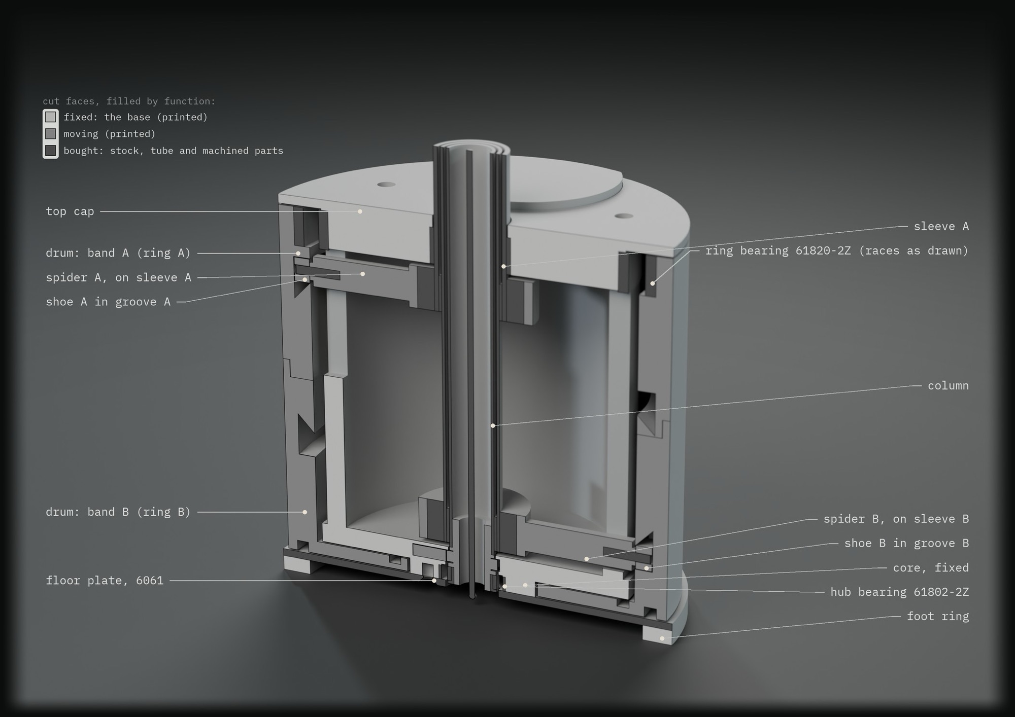
Each shoe rests on a groove flank cut 10.29° steep, under the 11.31° friction angle, so the head's weight cannot turn the ring. The detents only click and the end stops only stop: neither holds a pose.

Specified intent · provisional friction

The base in section at STOWED, cut faces filled by function: the drum's two bands, the spiders and the shoes in their grooves. Render from CAD
The angles and why the margin is provisional

The flank is 10.29° against a friction angle of 11.31° at the provisional μ 0.20: a holding margin of 1.02°. The selection rule asks for at least 2° at the lowest measured μ, so the groove lead is chosen after the friction coupons are measured; the band holds down to μ 0.184. Lifting the detent ball takes 89 N·mm at the ring.

06 — Found and fixed

Caught in the model, not in a print

Three problems the model caught.

The split drum

Problem

80.2° overhang

The two shoes' loads point opposite ways at every lead and angle, so in a one-piece drum one of the two locking flanks would print face-down.

Fix

≤ 45° overhang

Two bands, ring A printed upside down and ring B upright, each locking flank face-up, joined at a lapped seam.

Designed · model

The floor plate

Problem

0.48 mm sag

A 2.5 mm printed floor plate under a 2.0 kg lamp sinks 0.30–0.48 mm at the rim and closes ring B's 0.5 mm running gap.

Fix

16 µm

The same plate in 6061-T6, 23–34× as stiff in bending: the rim gap stays at least 0.48 mm, for 73 g more.

Designed · model

Rack B's backing roller

Problem

4.3 mm off the mesh

A 5 N push on the stowed head bent rack B's blade away from the tilt pinion: the head front moved 13.7 mm and the teeth parted past their working depth.

Fix

1.92 of 2 mm engaged

A flanged ball bearing on a dowel behind rack B, opposite the mesh: the deflection under the same push is 1.65 mm (base held), against a 2 mm target.

Specified intent · model

07 — Exploded

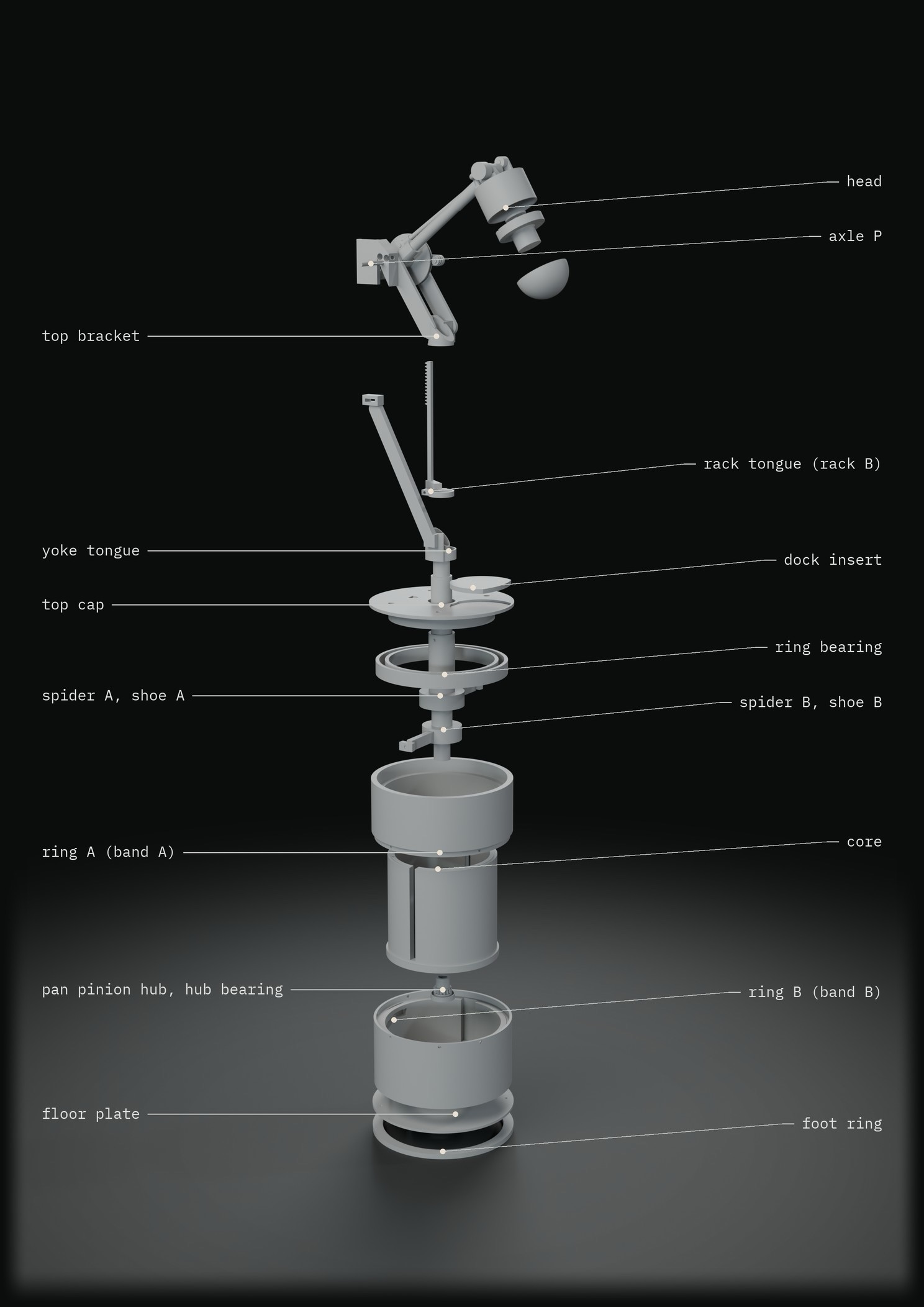
One stack, one axis

One stack on one axis.

67 drawn parts (79 pieces) in 12 layers out from the fixed core. 12 of them change shape with the groove lead, so they are made after the friction test sets it.

Designed · counted on the model

The floor plate, the stop pin, the cord carrier and the foot are fitted last, after the ring is set at TASK: the explode shows where each part sits, not the build order.

Exploded at TASK, layer by layer out from the fixed core: 67 drawn parts. Render from CAD

08 — Evidence, honestly

Designed and specified; nothing measured yet

What is met, what is not, and what gets measured.

Every figure here comes from the model and carries its level. Two targets are not met by design; they are shown, not hidden. Nothing has been measured yet: of 97 recorded claims, 40 are designed and 57 specified intent.

Targets against the model
FigureModelTargetStatusLevel
Free play through the ring, ring only (R-12a)2.71 mm≤ 0.5 mmnot met by designSpecified intent · fit model
Play under a reversing 5 N push (R-12b)17.07 mm≤ 17 mm (provisional)not met by designSpecified intent · fit model
Head deflection under 5 N, base held (R-12)1.65 mm≤ 2 mmmet by designDesigned · beam model
The same, standing on its foot1.68–1.97 mm≤ 2 mmmet by designDesigned · beam model
Holding margin, flank under the friction angle1.02°≥ 2° once μ is measureddecided by a test (TP-01)Specified intent · provisional friction
Detent breakout against the floor, at μ 0.201.65–1.91×1.5–2×met only at the provisional μDesigned · provisional friction

31 targets at the CAD freeze: 1 accepted by the owner, 14 met by design, 9 decided by a test, at assembly or on receipt, 5 not set, 2 not met by design; 0 measured.

What gets measured next, and how

The pass criteria were written down before any reading, and the analysers stay frozen until real data arrives.

The tests and their pass criteria fixed before data

TP-02 · fits ladders

Clearance and press ladders, each bracketing its fit; a ladder that does not bracket is reprinted, never extrapolated.

Specified intent · test protocol

TP-01 · flank friction

2942 g on the shoes (9.62 N per shoe). Pass: run-in μ spread ≤ 0.06 with CV ≤ 15 %; |μ run-in − μ fresh| ≤ 0.05; no cracking or transfer; the lever end moves ≤ 1 mm under hold.

Specified intent · test protocol

The selection rule

Holding margin ≥ 2° at the lowest corrected μ; lamp ≤ 2000 g; nested gap ≤ 15 mm. The rule sets the lead; the 12 lead-dependent parts are made after it.

Specified intent · fixed before data

Phase 3 · the prototype

Free play R-12a ≤ 0.5 mm and R-12b ≤ 17 mm; deflection ≤ 2 mm under 5 N; the base walk at desk μ ≥ 0.6; the detent's breakout 1.5–2×.

Specified intent · targets

09 — Next

The prototype

Next: the prototype.

  • 01The fits coupons are printed and measured on the bench.
  • 02The friction coupons are run, with the analyser frozen before the data.
  • 03The selection rule sets the groove lead; the 12 lead-dependent parts are made.
  • 04The prototype is assembled, and every target above is measured on it.

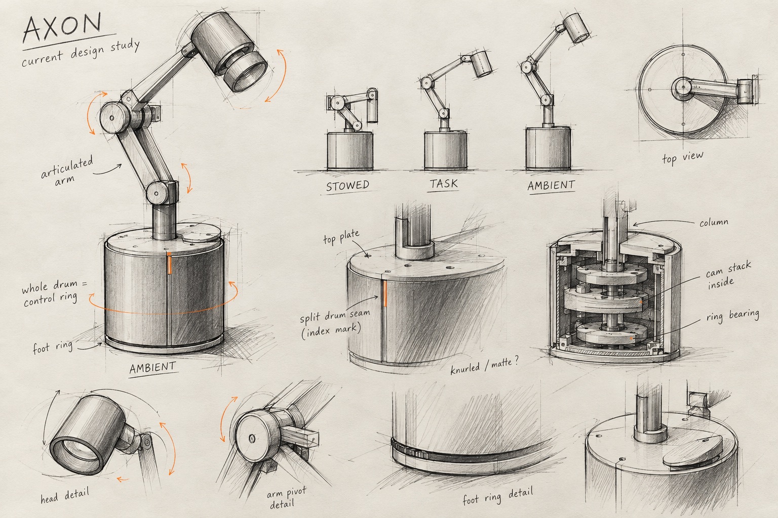
The starting point for the styling phase

Design study over the frozen CAD, October 2026 (AI-assisted). Styling ideas, not decided: head shape, knurled or matte drum, index mark on the split seam.
Design study over the frozen CAD, October 2026 (AI-assisted). Styling ideas, not decided: head shape, knurled or matte drum, index mark on the split seam.AI-assisted visual

10 — On the desk

Renders from CAD · nothing built

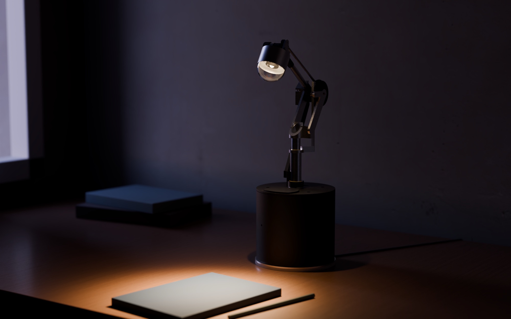
On a desk, at dusk.

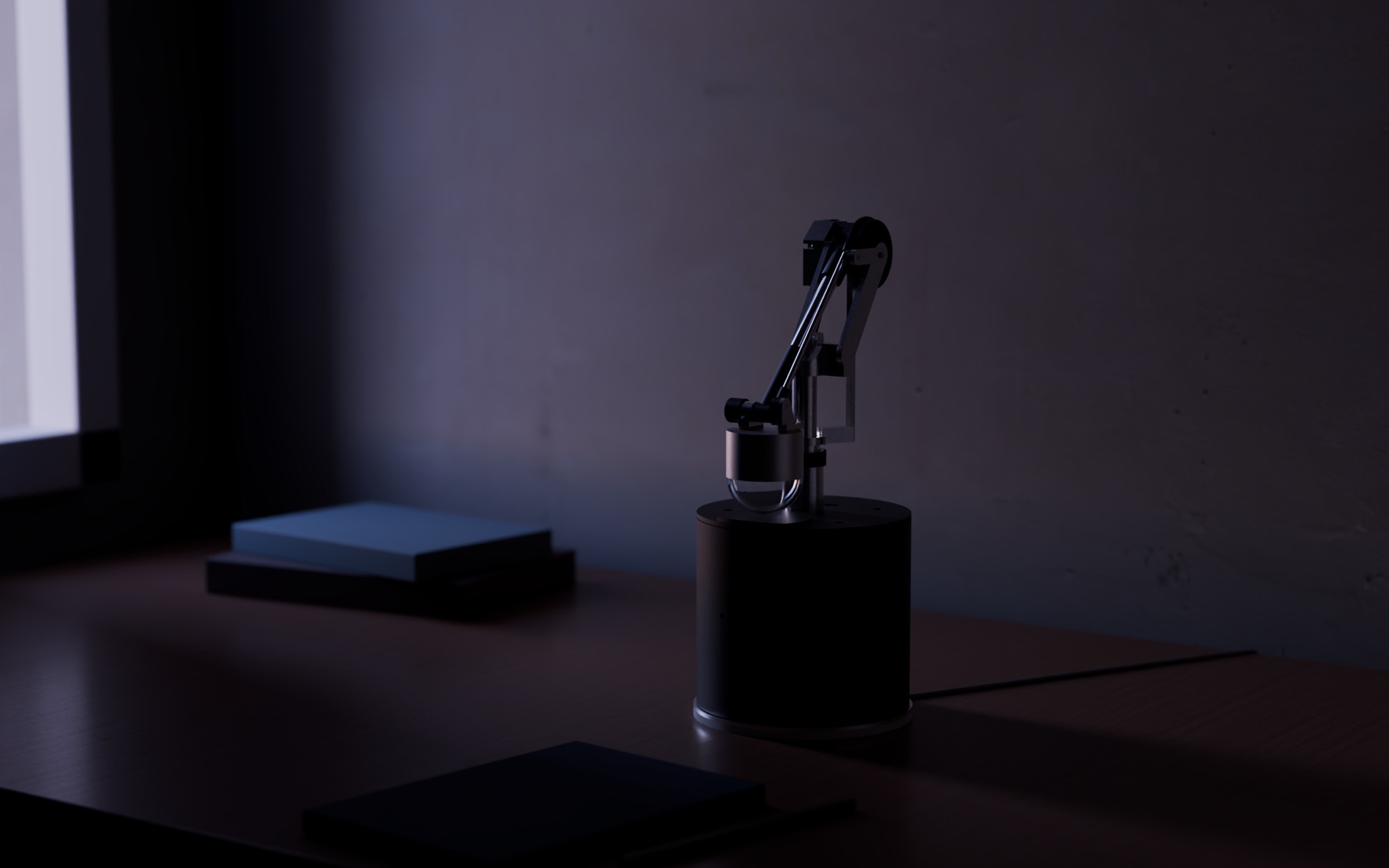
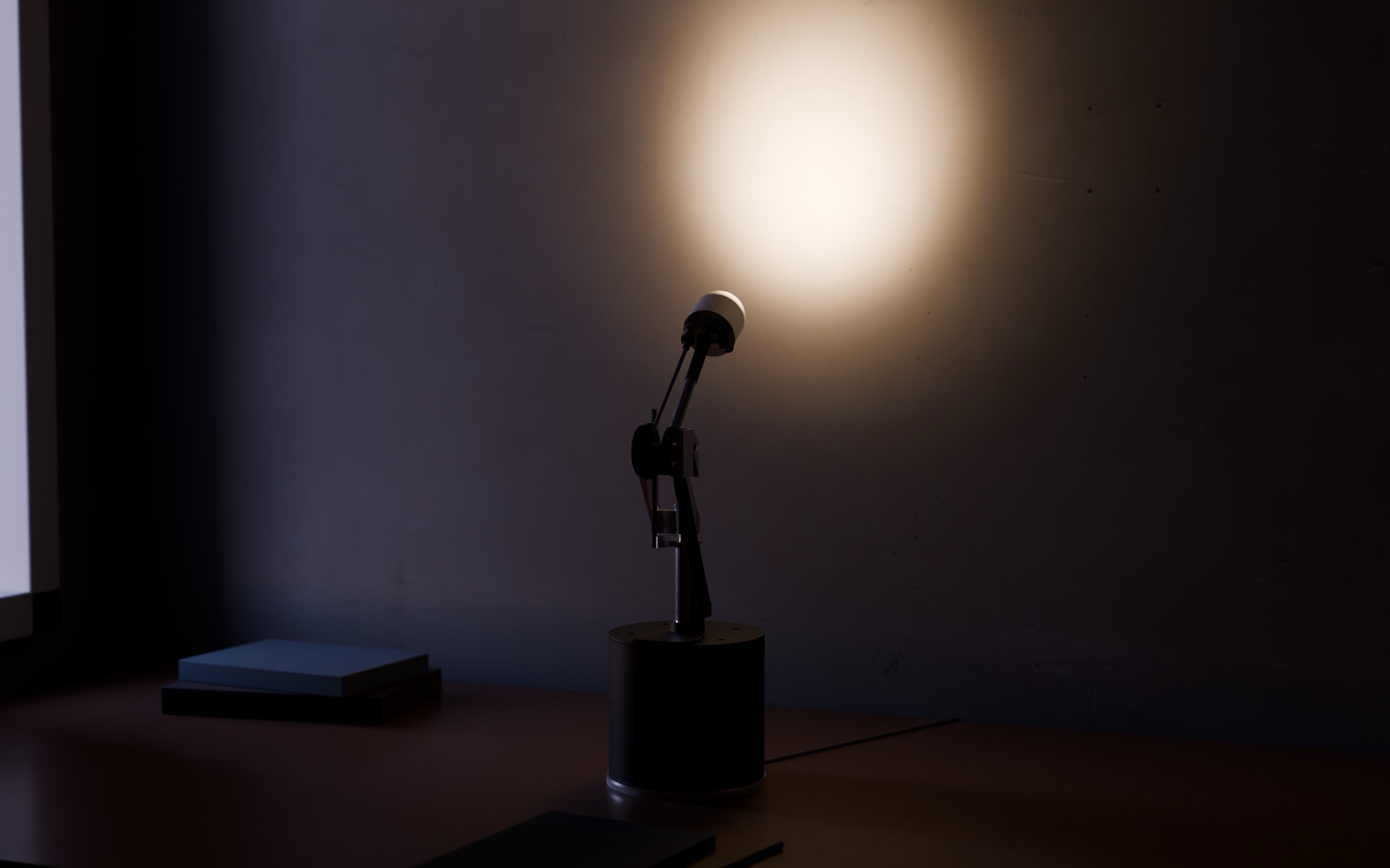
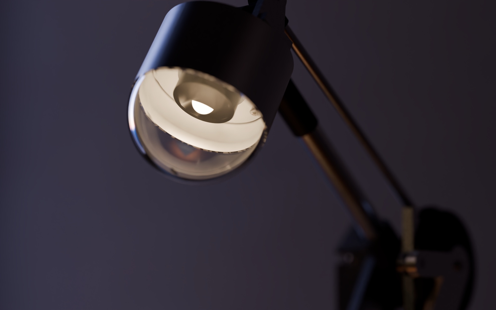
Renders of the frozen CAD in its three poses and close up, in the materials specified for the build. Two finishes are assumed until chosen: matte black for the printed parts and a clear anodise on the head's can and rear plate. Nothing is built, and no figure on this page rests on these pictures.

Render of AXON at TASK on a walnut desk at dusk: the head tilted down and lit, a warm pool of light on a notebook and a pencil; the round base, the column and the arm against a plastered wall.
TASK, ring at 170° · lit, the beam on the notebook · Render from CAD, not a built part
Render of AXON at STOWED on the same desk, switched off: the head lowered onto the top of the base, the arm folded upright behind it, in the blue light of dusk.
STOWED, ring at 0° · switched off, the head docked · Render from CAD, not a built part
Render of AXON at AMBIENT: the column raised and the head turned to the wall, throwing a soft round patch of warm light onto the plaster above the desk.
AMBIENT, ring at 270° · the head turned to the wall · Render from CAD, not a built part
Render, close up: AXON's head at TASK, lit, seen from slightly below: the can, its clear dome and the optic glowing inside, the arm out of focus behind.
TASK, ring at 170° · the head close up, the optic through the dome · Render from CAD, not a built part

The specified screws, the cord's exit and the reading lines are added from their specs; nine screws whose type is not chosen yet are left out, their holes shown empty, and the index mark's size and the cord's run across the desk are assumed. The beam follows the optic maker's file measured with a similar LED, its brightness set for the picture. The desk and the room are set dressing.

11 — Project status

CAD-developed concept
Stage
CAD-developed conceptThe product modelled in CAD to the depth the page states — exterior, key interfaces and the checks listed. Not built or physically validated.Designed and analysed — prototype in progress
Role
Mechanism, kinematic synthesis, parametric CAD and analysis
Project type
Independent project
Year
2017 concept · 2026 engineering
Tools
Python · build123d · Blender (Cycles)
What exists
The frozen parametric CAD (67 drawn parts, 79 pieces), its analyses, the renders and a case study.
Physical evidence
None yet: the first print runs are test coupons for friction and fits.
Not claimed
  • Any measured value: nothing has been built or tested.
  • Material and colour: the clay renders are toned by function; the desk stills assume matte black for the printed parts and a clear anodise on the head's can and rear plate, neither chosen.
  • Cycle life, torque feel and backlash at the head: their targets are not set yet.
  • Styling: the design study's head shape, drum finish and index mark are ideas, not decided.
Still open
  • Free play through the ring 2.71 mm against ≤ 0.5 mm and under a reversing push 17.07 mm against ≤ 17 mm (provisional): not met by design, measured in Phase 3.
  • The groove lead waits for the measured flank friction (TP-01); the lead-dependent parts are made after it.
Images
Renders from the frozen CAD: clay toned by function (fixed, moving, bought; not a material or colour proposal), and four on a desk at dusk in the build's materials, two finishes assumed; the viewer draws the same CAD's geometry, reduced for the web, moved by its own pose table. The chart is drawn from the kinematic model's results. No photographs: nothing is built yet. The origin's drawing and the design study are AI-assisted visuals made in 2026, labelled at each image; the drawing redraws the first idea, it is not a 2017 document.