MALINYX

Industrial · Ergonomic carry system

ECS

My original carry system for e-bike commuters, re-engineered in 2026: a load body on side rails and a spine pivot meant to move with the rider, with the mechanism measured on the model.

Role
Original design, mechanism, Rhino modelling, re-engineering, renders
Project type
Own design, re-engineered
Stage
CAD-developed concept
Year
Original 2020 · re-engineered 2026
Tools
Rhino
Images
3D renders

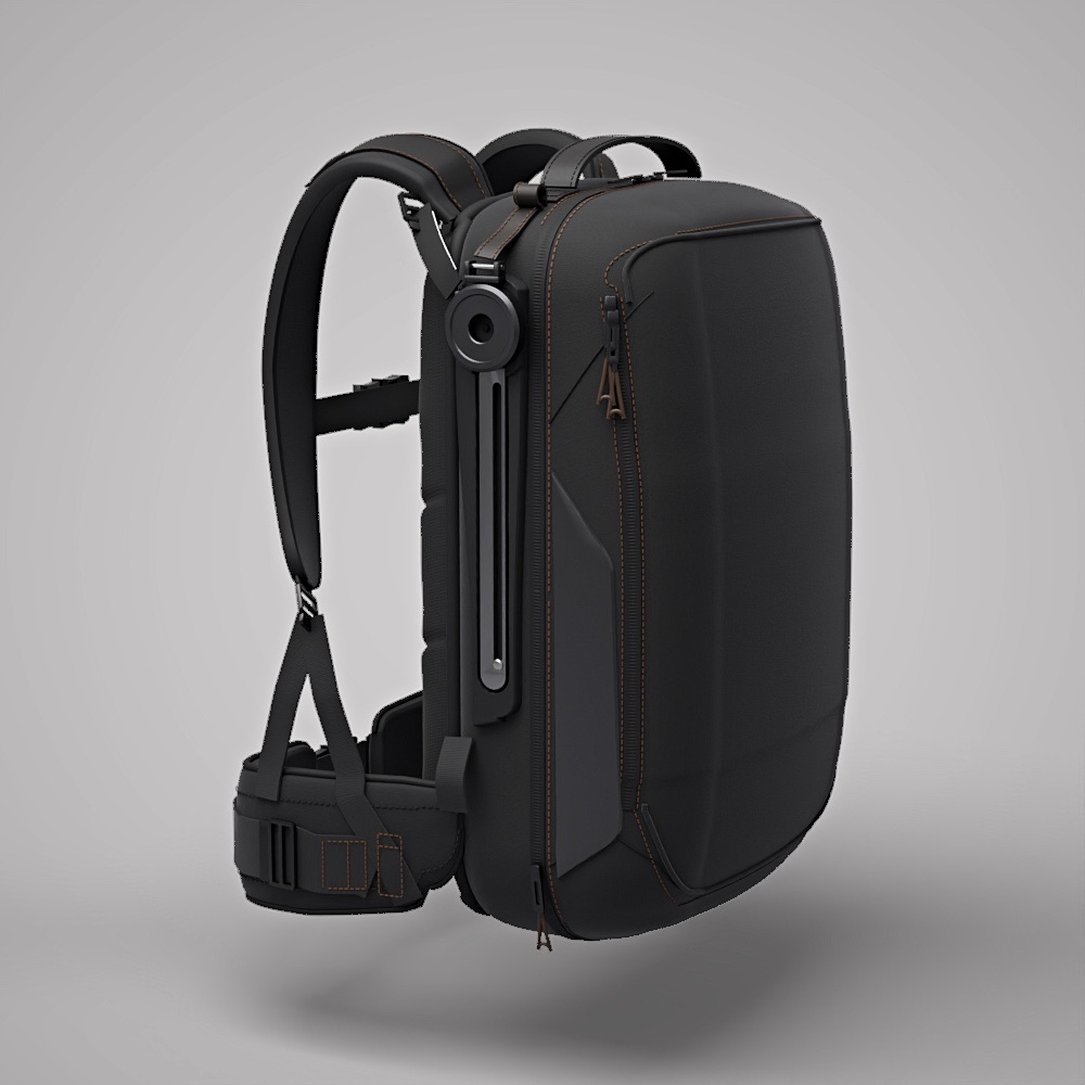
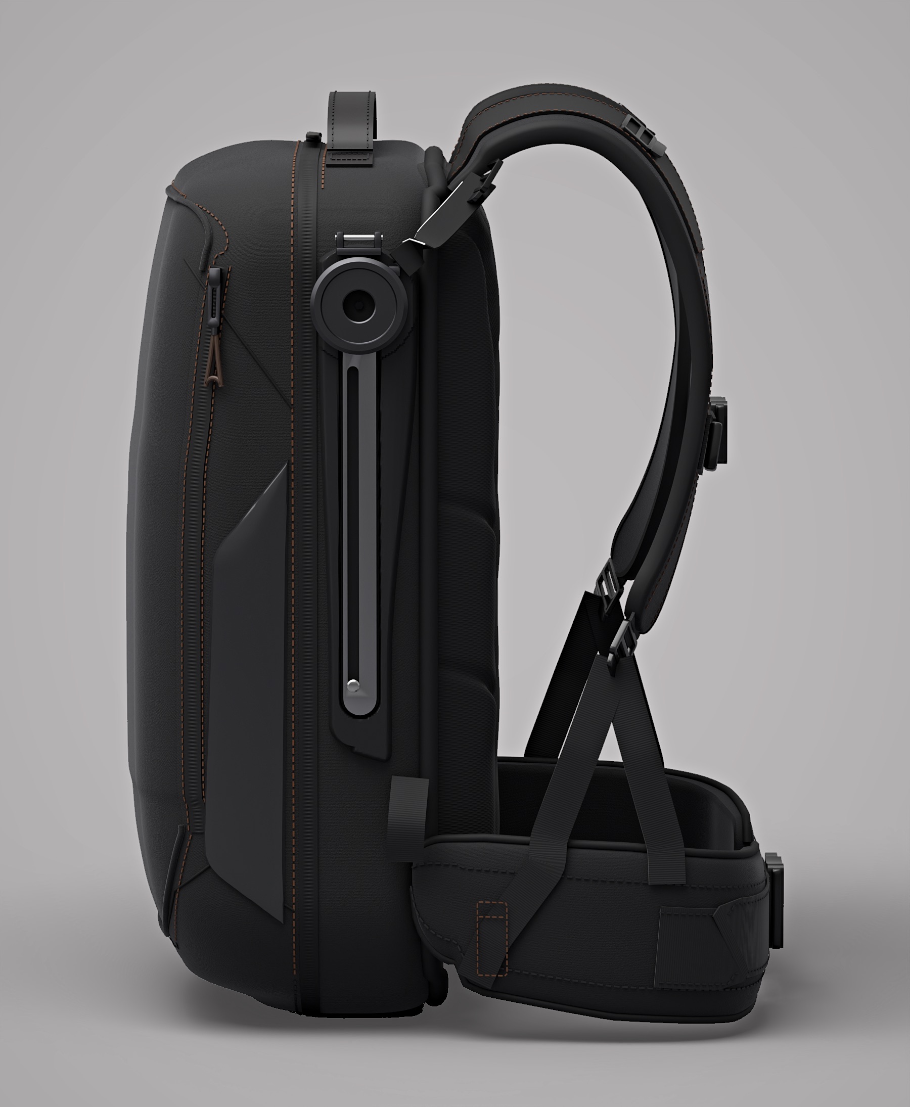
The packshot of my original design, as the 2026 model. Drag to turn it.

01 — The product in 10 secondsECS

Carry that moves with the rider.

What it is
A backpack-format carry system for e-bike commuters: a load body of about 20.5 L on side rails, a spine pivot and a harness that splits onto belt wings.
Who it is for
Urban e-bike commuters riding with a load.
The problem
When the rider leans forward, the load’s lever on the hips should get shorter.
What is different
A tension-shortening harness is meant to pull the load down and in. Measured on the 2026 model, it slides 11.6 mm against a 100–150 mm target.
Load-body outer volume, measured on the 2026 model (not usable capacity)Measured on model
20.5 L
Load-body slide at a 35° lean · target 100–150 mmMeasured on model
11.6 mm
A6 tension strap length needed, within the sheet's 80–260 mmMeasured on model
253.5 mm
Unintended clashes beyond the screening threshold, in three poses (rigid 0.3 mm, soft parts 1–3 mm)Screened on model
0
02 — The design challenge

The same design. Now it can be measured.

ECS was documented in ten component sheets, kinematic sheets and a cardboard mock-up. The 2026 model keeps the design and asks a plain question: does the mechanism, as drawn, do what the sheets say?

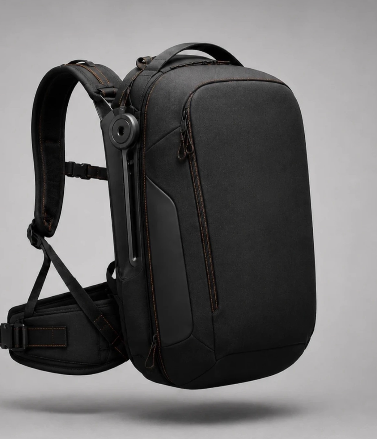
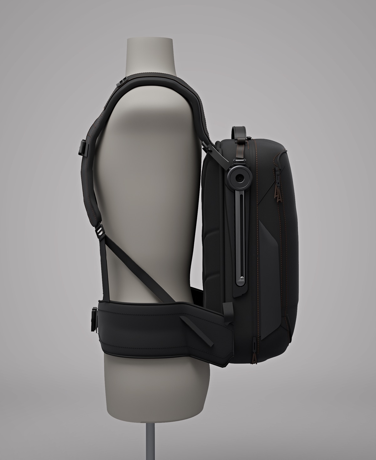
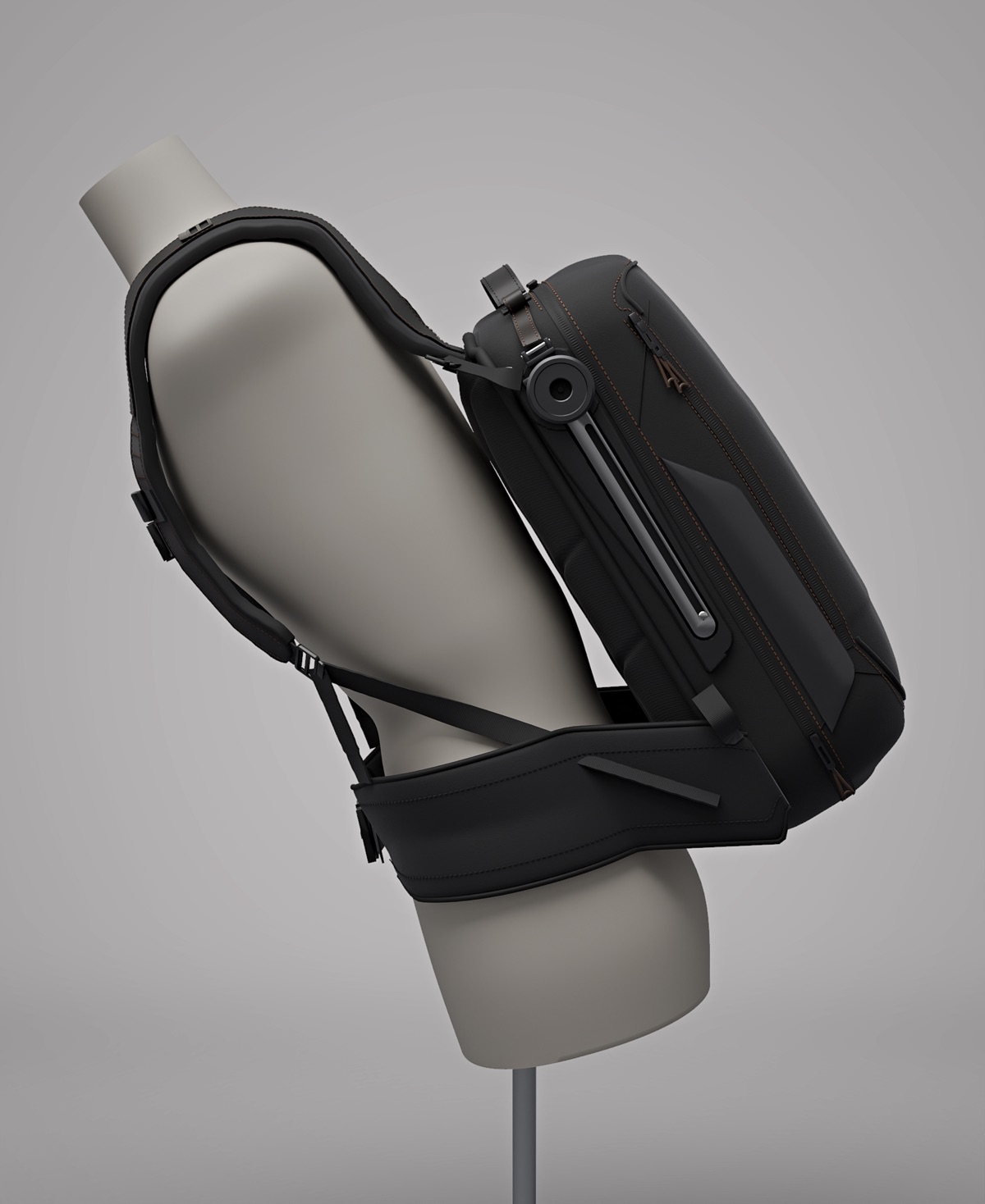
ECS — the original, before the rebuildECS — the 2026 rebuild
Original · 2020 · design and image by Bahareh Arianejad.

Original design image (2020) and 2026 model — different cameras and lighting.

03 — My contributionOwn design, re-engineered

What I did.

My own design: the original and its 2026 re-engineering.

  • Original concept and mechanism (2020)
  • Rhino modelling of the 2026 model
  • Mechanism measurement
  • Interference screening
  • Technical drawings
  • Renders
04 — Design response3 decisions · reason · evidence

The decisions that shaped it.

Decision 01

A load body that can follow the lean

The load body rides on side rails and a spine pivot with ±30° of travel, so it can move as the rider leans.

Designed
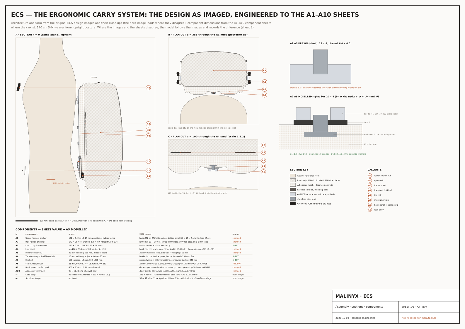
The design, engineered to the A1–A10 sheets

Decision 02

A harness that shortens under lean

A tension-shortening harness is meant to pull the load body down and in toward the spine, shortening the lever between hip and load.

Designed · documented principle
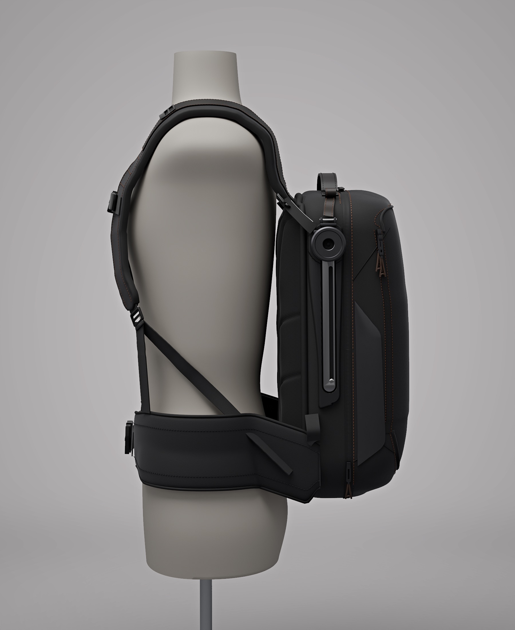
On the wearer form, upright

Decision 03

Measured, not tuned

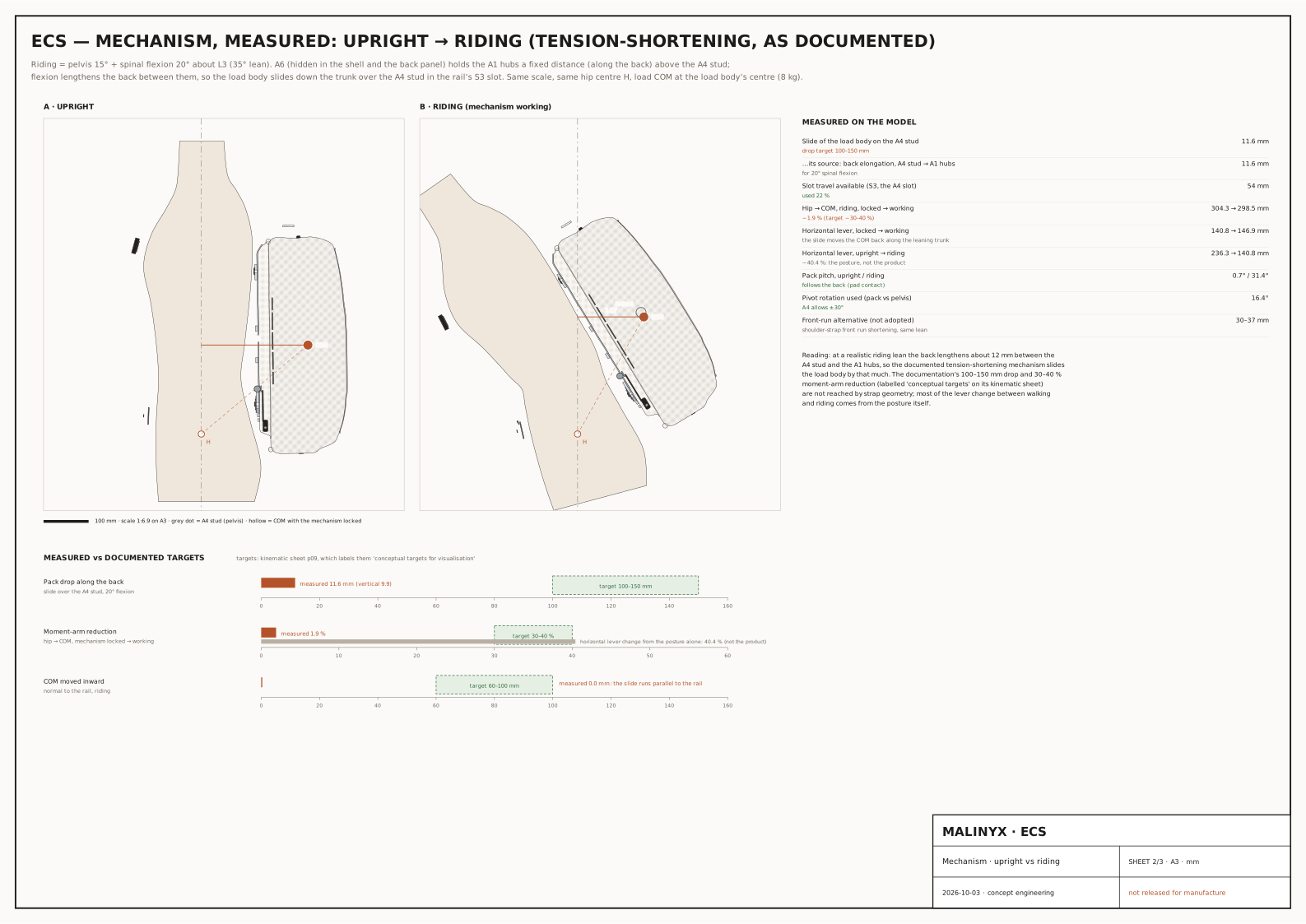
At a 35° riding lean the pivot turns 16.4° and the load body slides 11.6 mm, against a 100–150 mm target. The gap is reported, not tuned away: it is the next design problem.

Measured on model
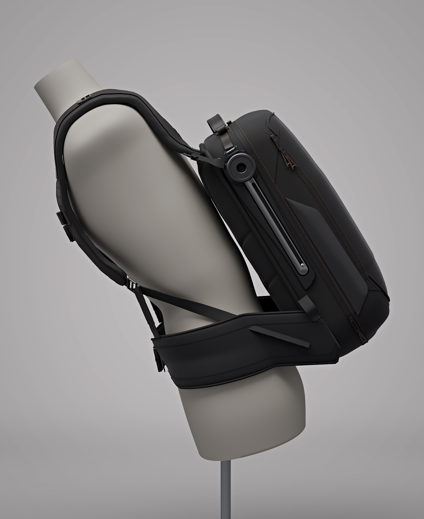
On the wearer form at a 35° riding lean
05 — Product architecture & engineeringCAD-developed concept

How it is built.

CAD-developed architecture with the mechanism measured as documented. Unintended interferences are screened in the upright, riding and packshot poses (rigid parts at 0.3 mm, soft parts at 1–3 mm). The measured slide is far below the documented target — that gap is the next design problem, shown here as measured.

Key dimensions and their claim level
ItemValueLevel
Load body≈ 20.5 L outer volume (not usable capacity)Measured on model
Slide at 35° lean11.6 mm · target 100–150 mm (conceptual)Measured on model
Hip moment arm+4.3 % locked → working · target −30 to −40 %Measured on model
A6 strap length253.5 mm · within the sheet’s 80–260 mmMeasured on model
Engineering notes the longer story

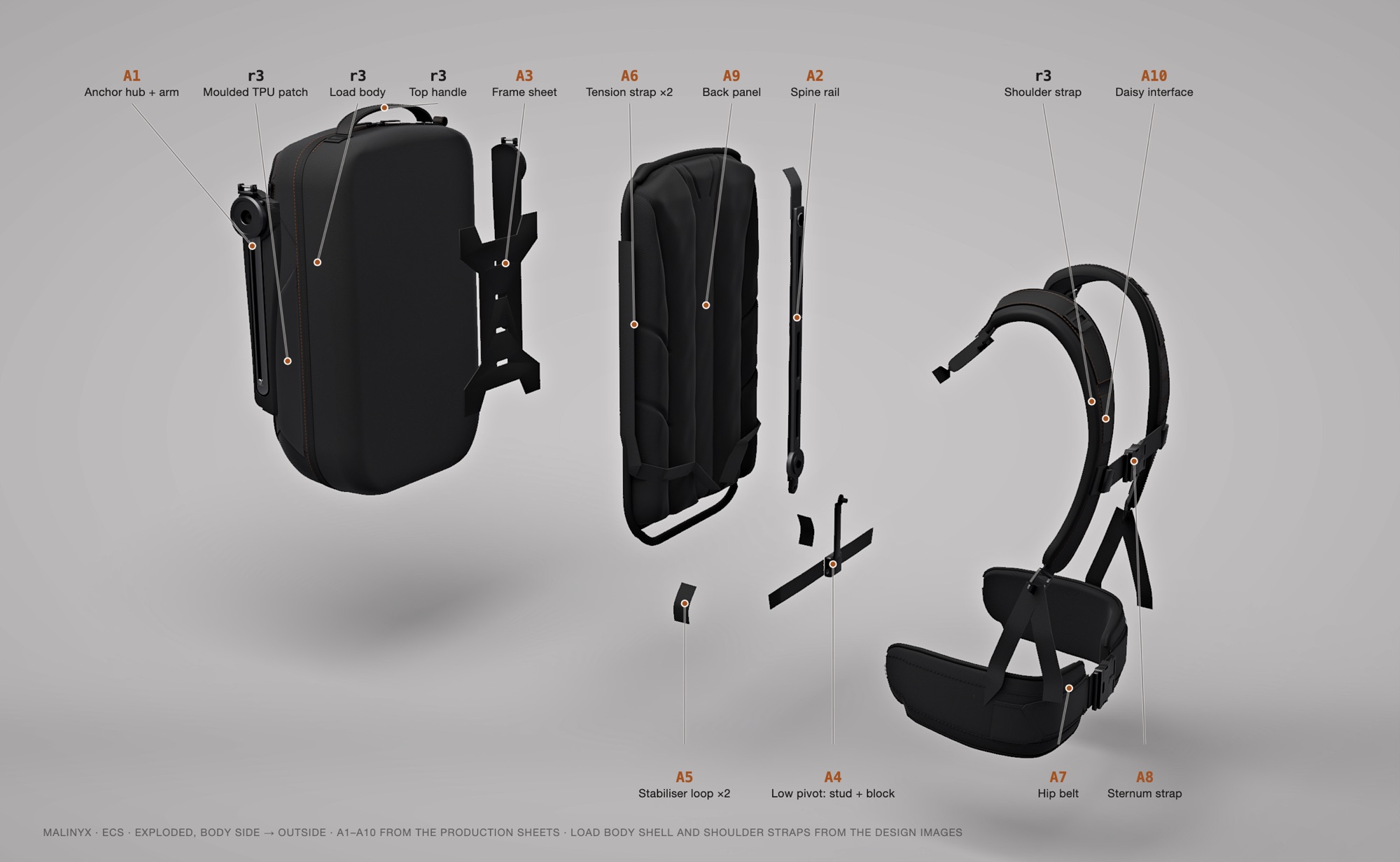
ECS was designed as a wearable load-transfer system for urban e-bike commuters. Under forward lean, a tension-shortening harness is meant to pull the load body down and in toward the spine, shortening the lever between hip and load. The original documentation describes it in ten component sheets (A1–A10), kinematic sheets and a cardboard mock-up.

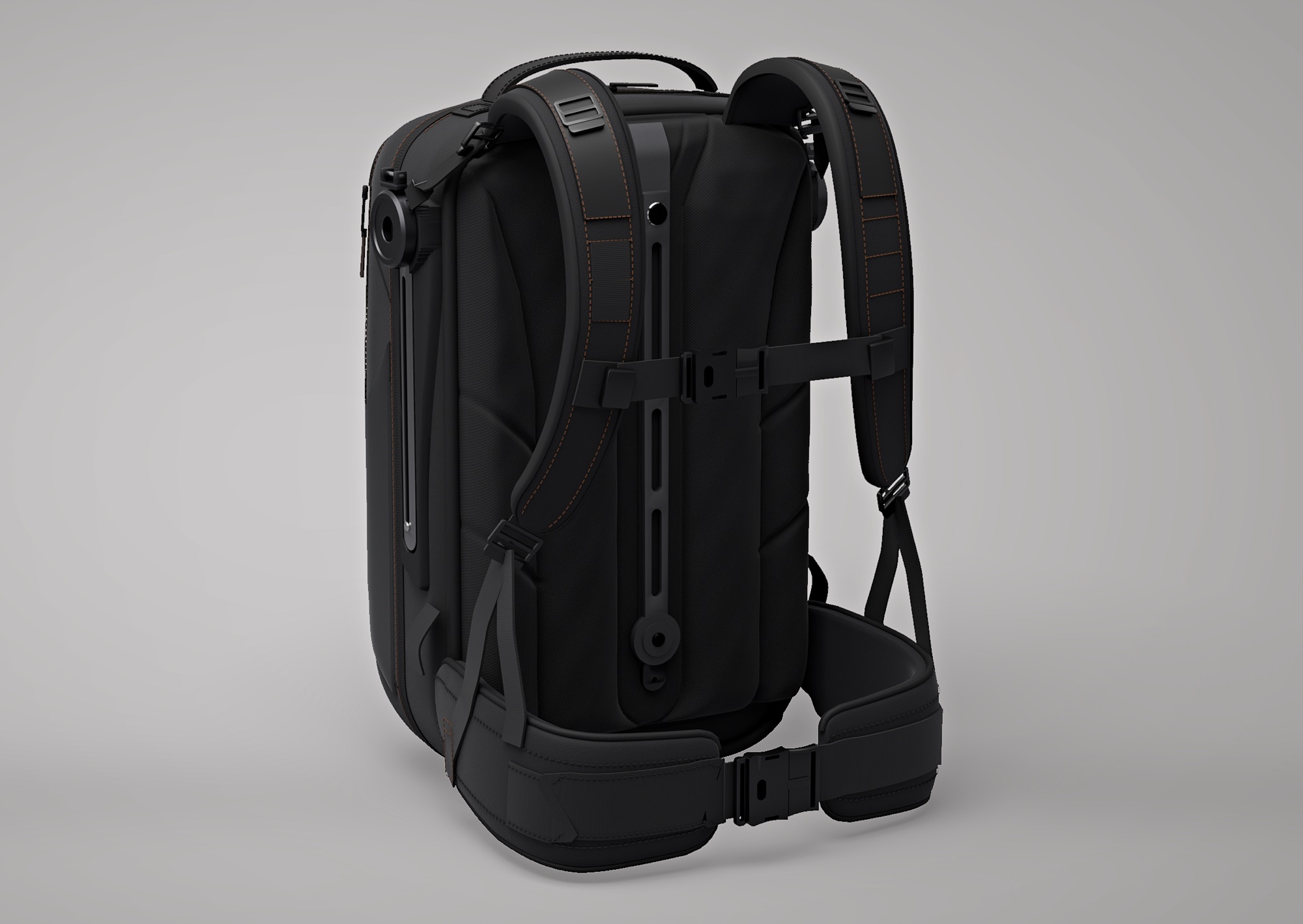
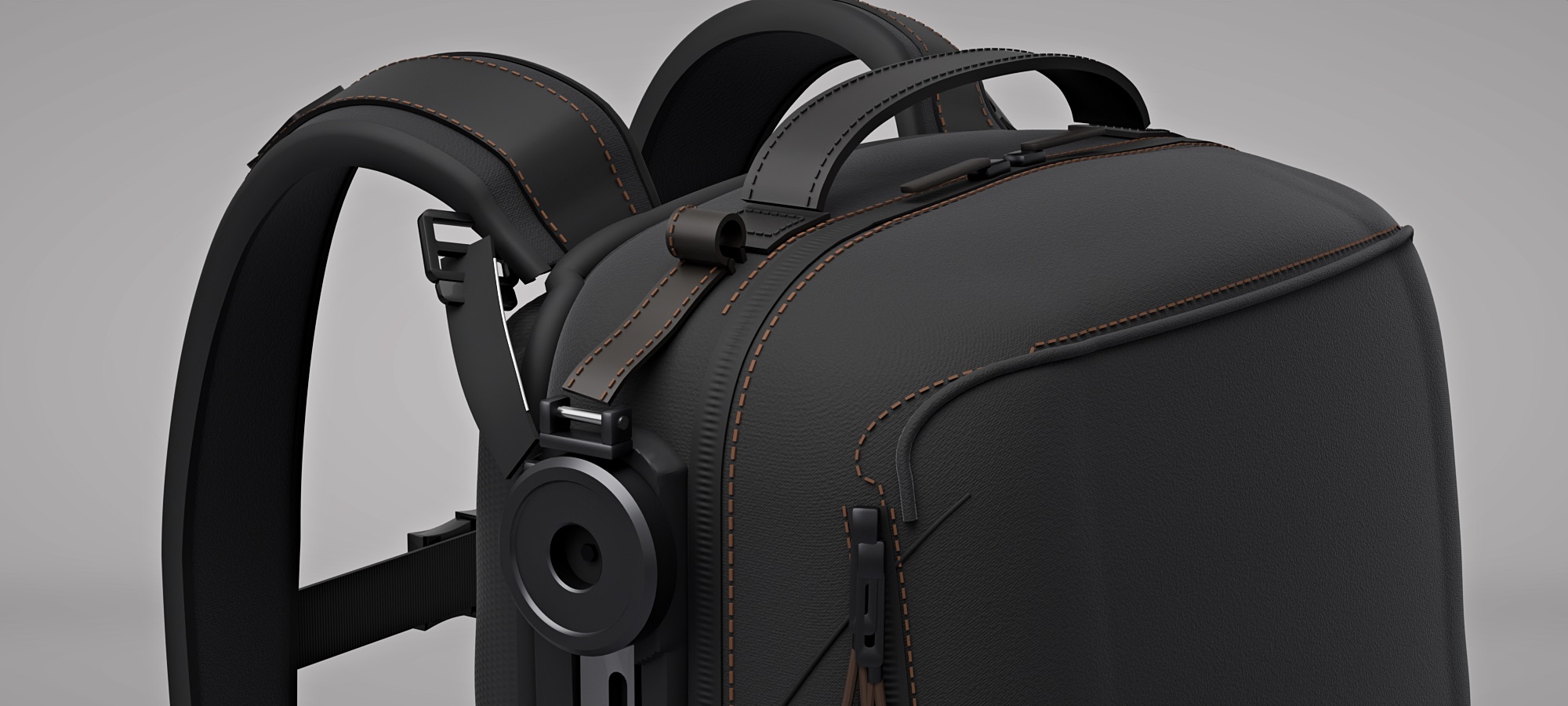
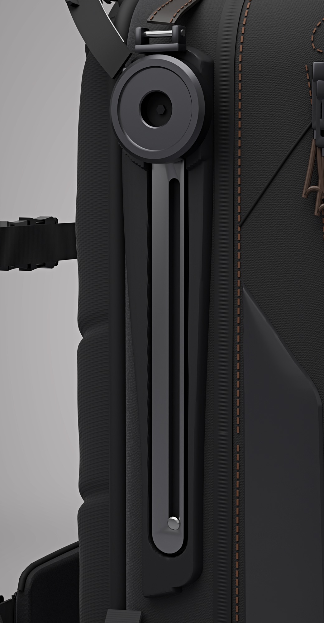
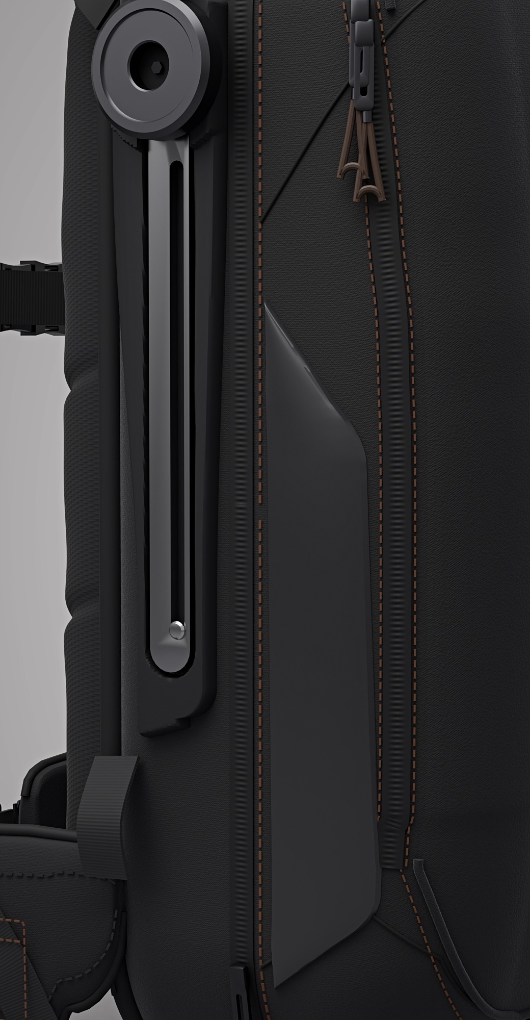
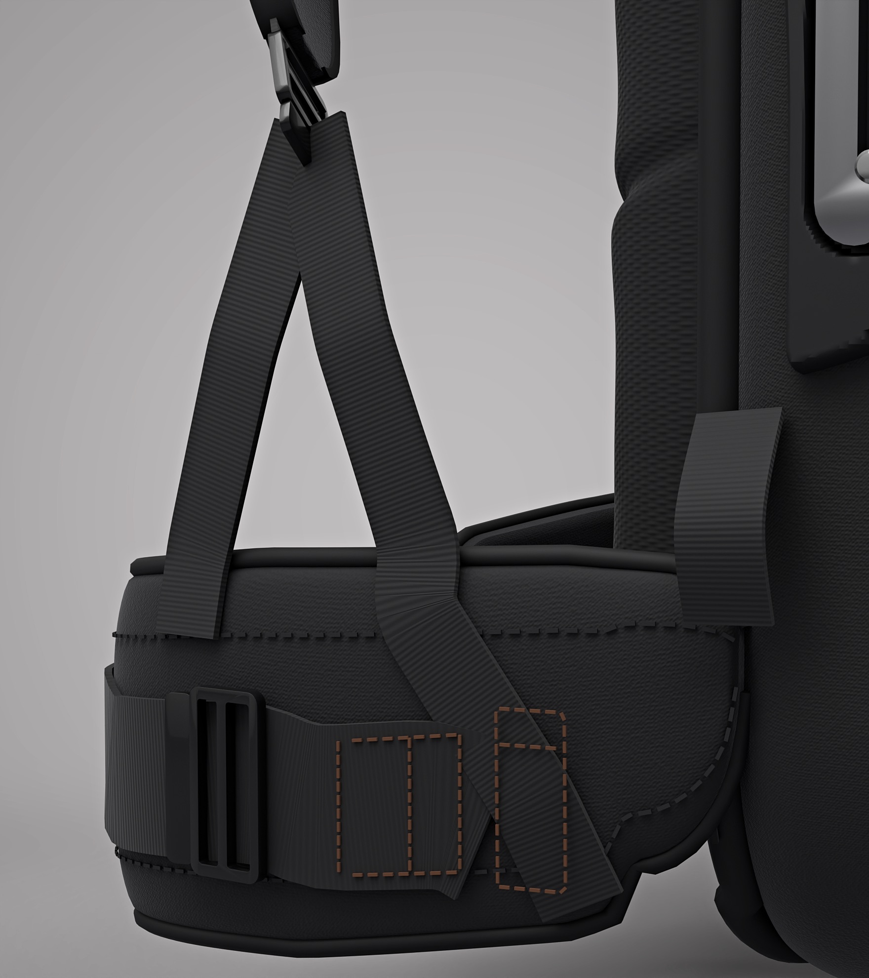
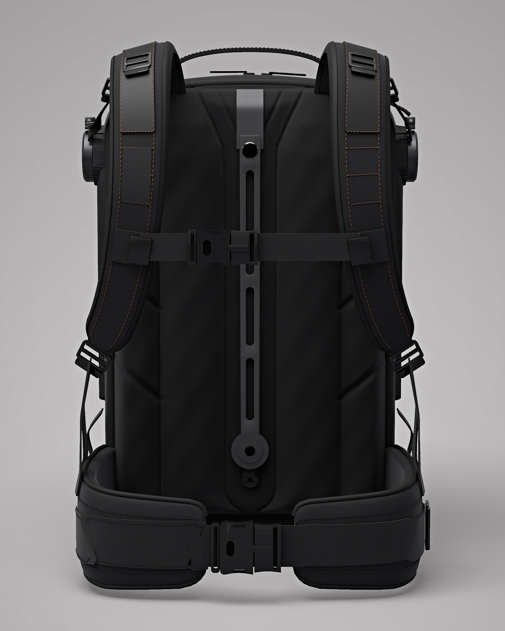
The 2026 model keeps my original design and takes component dimensions from the A1–A10 sheets where they exist. Where the design goes further than the sheets (the Ø52 gunmetal hubs on satin arms in moulded side plates, the slotted spine bar, the moulded TPU side patches, the copper-stitched shoulder straps that split into two legs onto the belt wings), the 2026 model follows the design and records the change.

Then the mechanism was measured, as documented. At a 35° riding lean the load body slides 11.6 mm (9.9 mm vertically) and does not move inward. The sheets set a 100–150 mm drop and call that target conceptual. On a bike, the −40 % lever change comes from the rider's posture, not the product; the mechanism itself lengthens the hip lever slightly (+4.3 %). That gap is the next design problem, and it is shown here as measured.
06 — Drawings

Drawn from the 2026 model
Sheet 1 · the design, engineered to the A1–A10 sheets
Sheet 2 · the mechanism measured, upright → riding
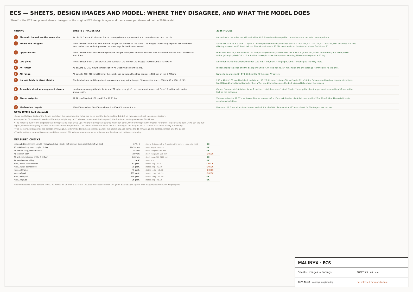
Sheet 3 · where the sheets, the images and the model disagree
07 — CMFColour · material · finish

Materials as designed.

Material intent read from the original design images; no CMF specification exists.

  • Gunmetal

    Ø52 hubs

  • Satin metal

    Hub arms and spine bar

  • Moulded TPU

    Side patches · Satin

  • Copper stitching

    Shoulder straps

09 — Project status

CAD-developed concept
Stage
CAD-developed conceptThe product modelled in CAD to the depth the page states — exterior, key interfaces and the checks listed. Not built or physically validated.
What exists
The original documentation (A1–A10 sheets, kinematic sheets, a cardboard mock-up) and the 2026 model with drawings.
Physical evidence
A cardboard mock-up in the original documentation — form only.
Not claimed
  • Load-transfer or comfort performance
  • Strap, fabric or joint strength
  • Manufacture
  • Prototype validation, although the status table in the original documentation says so: the physical evidence is a cardboard form mock-up only
Still open
  • Slide of 11.6 mm against the documented 100–150 mm drop, and 0 mm inward against 60–100 mm: the mechanism as drawn does not reach its targets.
  • Hip moment arm +4.3 % (140.8 → 146.9 mm), locked → working, against a documented −30 to −40 % (conceptual).
  • The pivot (A4) and tension strap (A6) sit hidden inside the spine strip and the shell, as in the design: a change to the documented layout, still to confirm.
  • Sternum span of 188.5 mm, outside the sheet's 200–210 mm.
  • Estimated masses differ from the sheets: back panel ≈ 299 g against 110 g stated, spine rail ≈ 70 g against 28 g.
  • Still to decide, where my design views differ: hub height and size (Ø52, or Ø31–39 in the side view), sternum height, belt depth, and the back silhouette (top handle, side hubs, one strap leg, the top loop).
Images
Renders of the 2026 model, composited on a grey studio backdrop matched to my original design images; the mechanism views are on a wearer form. The original design image is shown for comparison.